The
impending death of the multi-billion dollar Iridium constellation is
without any doubt a great setback for the satellite communications
industry, and microwave communications industry as a whole. What was to
be a bonanza, a new frontier of truly global mobile communications, has
collapsed into a mire of insolvency and massive commercial losses.
Recent mass media reports suggest that the constellation
will very soon be destroyed, by slowing the satellites into descending
orbits, to burn them up in the upper atmosphere.
The demise of Iridium is a sad outcome for the world's
first Low Earth Orbit (LEO) communications system. The important
question which we can ask is that of what persuaded so many engineers
and investors to commit so much to a risky venture of this nature. What
was the perceived advantage which led them to this eventual commercial
quagmire and final disaster ?
The summary answer is microwave propagation. However, to
appreciate the reasons fully, we must delve a little deeper into the
problem. This indeed will be the subject of this month's feature.
Basic Issues in
Propagation
The problem of getting a radio frequency signal, in the
decimetric, centimetric or millimetric bands, between two geographically
well separated antennas, is in principle simple but in practice messy.
In a genuine free space environment, typified by a
crosslink between a pair of satellites in higher orbits, or a pair of
spacecraft in interplanetary space, the problem is as simple as
pointing the antennas at each other and launching the wave into space.
Since the wave obeys the well known 1/r^2 Friis equation, it will
diminish in intensity with the inverse square of distance. The power
detected by the receiver will depend upon the respective gains of the
two antennas, the transmitted power level, and the distance between the
transmitter and the receiver. Providing that there is no powerful radio
source, such as the sun, within the mainlobe of the receiver's antenna,
the signal to noise ratio, and thus achievable throughput per
bandwidth, will depend wholly upon the Friis equation and the noise
performance of the receiver.
The bit rate achieved across such a link will thus
depend on the distance, antenna specs, power output and quality of the
receiver. Indeed, every undergraduate comms engineer will have solved
this problem in a third or fourth year University assignment or exam
paper.
Alas, the "free space" model of radio propagation is
very much a "best case scenario", and one which is not frequently
encountered in daily operation, with the exception of trivial cases
like microwave links between adjacent buildings.
Mother nature, having little respect for the
expectations of engineering undergraduates, likes to complicate things
a little, and introduces a number of interesting, albeit often
difficult to solve, obstacles in this game. These are the effects of
refraction, lensing, scattering, and absorption in the natural
environment.
The Atmosphere as
a Propagation Environment
Virtually all of the difficulties encountered in
microwave transmission, be it between terrestrial transceivers, or
satellite ground stations, stem from the physical properties of the
atmosphere.
The atmosphere is the gaseous shroud covering mother
earth, comprising mostly nitrogen, with a decent fraction of oxygen and
carbon dioxide, and at lower altitudes also water vapour or droplets.
The atmosphere obeys the pull of gravity, indeed the earth's gravity
well is what keeps it attached to the planet. Planets with weaker
gravity wells cannot maintain an atmosphere, and the gaseous shroud is
blown into space over time.
The effects of gravity are pronounced, and manifested in
decreasing atmospheric density and pressure with increasing altitude. At
the earth's surface, the temperature, density and pressure are highest,
as a result of which the propagation impairments are most pronounced.
The atmosphere is divided into layers. The lowest of
these is the troposphere, which extends up to about 11 kilometres,
depending upon the geographical latitude. In the tropics it may extend
up to 15 kilometres, due to the updrafts produced by massive tropical
rainbearing cumulonimbus clouds. The troposphere is the warmest, most
dense and wettest layer of the atmosphere. I like to call it the
"tropospheric soup" since it has, in propagation terms, the attributes
of a rich broth full of ingredients.
Above the troposphere is the stratosphere, the domain of
Concordes and supersonic military jets. Devoid of dense cloud, much
colder and thinner than the troposphere, the stratosphere is a much more
benign environment for microwave transmissions.
Whether we are considering a terrestrial link or a
satellite link, the effects of the atmosphere frequently dominate
losses in propagation. Designers of microwave links ignore it at their
peril.
Refraction Effects
Refraction is a physical phenomenon observed in any
medium which has a varying refractive index, and produces the effect of
bending a light ray or microwave beam. The atmosphere is exactly such
an environment, since its density and thus refractive index varies
significantly with changing altitude and weather conditions.
At a first glance one might think this is only an issue
for satellite transmission, but the curvature of the earth makes it an
issue even for terrestrial links overs tens of kilometres of distance,
should the beam be particularly narrow.
Refraction usually produces desirable effects, insofar
as it can allow a pair of stations to communicate over the horizon,
since the beam is effectively bent. It can also allow a satellite
ground station at high latitudes to see a geostationary satellite over
the equator, from positions which would appear infeasible
geometrically.
However, refraction is a double-edged sword. This is for
two reasons. The first is that refraction can also allow signals to
interfere with other links by propagating over the horizon. This problem
is exacerbated by a peculiar effect called "ducting", which can arise
when a meteorological effect called an inversion occurs. An inversion
happens when the layer of air closer to the earth's surface is colder
than the air above it. When this happens, usually under still and warm
conditions, the refractive index change in the atmosphere with altitude
is such, that a layer of the atmosphere behaves like a waveguide.
Microwaves which enter this layer, termed a duct, cannot escape. Like a
light ray trapped in an optical fibre, they will propagate far beyond
the horizon. I recall the odd experience, many years ago on a European
trip, of watching a TV broadcast from North Africa which had ducted
itself into central Europe !
Refraction can be an issue for many satellite links,
especially GEO links at extreme latitudes. A large temperature change
can cause link dropouts or interference.
In practical terms, refraction is a hindrance mostly to
GEO satellite links, due to the lower depression angle over the
horizon, with increasing latitude. Refraction effects are however
minimised with the use of an LEO constellation, since the satellite
within a cell is always at a steep elevation angle above the ground
station.
Lensing effects arise from a combination of refraction
and the earth's curvature, and usually are not significant.
Absorption and Scattering
Absorption and scattering are the dominant sources of
microwave band, and especially millimetric wave band transmission losses
in the lower atmosphere.
The primary source of absorption losses at all altitudes
is an effect called gaseous absorption, which results from the quantum
physical behaviour of atmospheric gas molecules. A gas molecule of any
species, such as nitrogen, oxygen, carbon dioxide or water vapour
experiences resonance effects, not unlike a tuning fork. This analogy is
a very good one, insofar as each of these molecules at an atomic level
is made up of several nuclei, held together by electromagnetic forces,
and therefore behaves in a manner not unlike balls held together by
springs. If you perturb the molecule, it will vibrate in a number of
possible modes, be they rotational, flexural or longitudinal, depending
on the shape of the molecule and the manner it was excited.
What is important for the microwave engineer is that
these resonances produce electromagnetic effects. If such a molecule is
placed inside a microwave beam, and if the frequency of the beam is
close enough to the resonance frequency of the molecule, the molecule
will draw energy from the beam as it is excited. If you put enough
molecules into the beam, an appreciable amount of power will be lost.
If we are trying to send a microwave signal between a
ground station and a satellite, the beam must pass through hundreds of
kilometres of atmospheric gasses. Therefore many deciBels of power can
be lost.
How much is lost depends upon the frequency of the
carrier wave, the pathlength through the atmosphere and local
atmospheric conditions.
In times past this was not a major issue, since at
frequencies below 10 GHz gaseous losses are almost irrelevant. However,
the water vapour molecule has a strong resonance at 22.235 GHz, and
moving into the millimetric band, the oxygen molecule has a cluster of
resonances around 60 GHz. Moving beyond 60 GHz, further water vapour
resonances arise above 100 GHz.
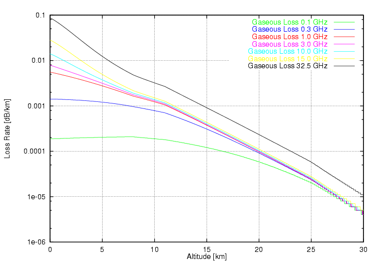
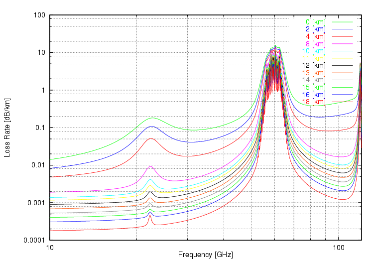
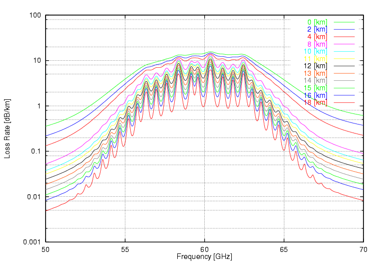
The collective effect of these resonances is depicted in
Figures 1, 2 and 3. Figure 1 shows the increasing effect with decreasing
altitude, Figure 2 shows the frequency dependency of these losses, for
various altitudes, and finally Figure 3 shows the detailed loss
behaviour around 60 GHz, all in dB/km loss rates.
The practical consequences of this behaviour are that
many frequencies in the millimetric band verge upon the unusable,
especially for link distances in excess of several kilometres. This is
of importance in local multi-point distribution schemes, where a signal
is fed through a fibre to a local microwave antenna head, but it is
also critically important for satellite links. Since the frequency
bands below 15 GHz are virtually saturated in OECD countries, there is
much pressure to start using frequencies above 15 GHz, especially for
satellite links. The 28 GHz sub-band has been very popular, since it
sits in a "trough" in the loss behaviour curve. Even so, the dB/km loss
is almost tenfold that at 10 GHz.
While this matters at shorter distances, it becomes a
"go/no-go" factor for satellite links. Also this is the reason why LEO
systems have significant propagation advantages over Medium Earth Orbit
(MEO) and GEO systems. In both latter instances, the elevation angle of
the beam can be very shallow, which introduces a significant increase in
the atmospheric pathlength the beam must propagate through. An LEO
system can be designed to ensure that the beam elevation angle is of the
order of 45 degrees or more, thus minimising the pathlength through the
atmosphere.
Gaseous losses are unavoidable as long as we situate our
antennas on the surface of the earth. They will vary somewhat with
increases or decreases in local humidity, but in principle, cannot be
escaped. Even under best case conditions of clear sky, they are ever
present.
Scattering losses are no less troublesome a problem in
microwave propagation, be it point to point links or satellite links.
While they vary significantly with local weather conditions, a
complexity within itself, they too cannot be avoided in most parts of
the world.
A scattering loss will arise when the microwave beam
encounters droplets or particles in the atmosphere. If these particles
are smaller than a wavelength, an effect called Raleigh scattering
occurs, whereby the droplet or particle reflects a small proportion of
the impinging energy, not unlike an aeroplane in a radar beam. Indeed
the physics involved are fundamentally the same.
How much energy is scattered and never reaches the
receiver depends upon the size of the scatterers relative to the
wavelength, their density per volume of the atmosphere, the pathlength
through the scattering environment, and the dielectric properties of
the scatterers.
The most common source of scattering losses is the
humble cloud. Made up of microscopic water droplets, clouds vary
significantly in moisture content and thus lossiness. Low density
clouds like stratus, stratocumulus and puffy little summer cumulus
clouds introduce some losses, increasing with frequency, but are almost
insignificant in comparison with dense water laden rainclouds, and
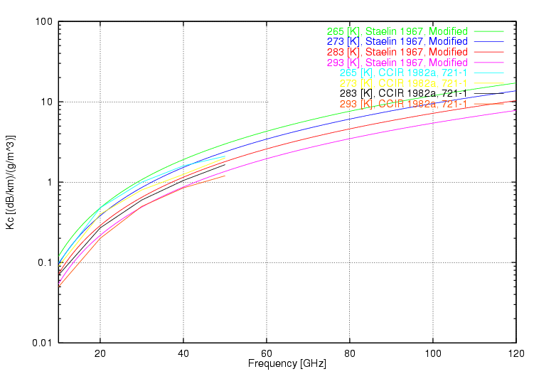
especially the cumulonimbus thunderstorm cloud. Figure 4 depicts the
loss coefficient in dB/km per cloud density, in grams per cubic metre,
against frequency and temperature. At 40 GHz a cloud with a density of
10 grams/m^3 will introduce a loss of 8-20 dB/km. If the beam must
travel through 3 km of such cloud, the total loss varies between 24 to
60 dB, which is most instances renders such a link unusable.
While cloud related losses are usually not an issue
below 15 GHz, they become an increasingly serious issue with increasing
frequency, and there are no troughs in the curve whereby an engineer can
cheat ! The millimetric bands above 40 GHz are virtually compromised for
satellite work, and even the Ka band 20-35 GHz window in gaseous loss
behaviour is rather exposed.
Of course the same caveats concerning pathlength also
apply, so for a satellite link, the steeper the elevation angle, the
better.
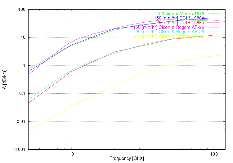
Where there is cloud, there is frequently rain, and rain
like cloud is a scattering environment. Rain droplets however tend to
be much larger in size, compared to cloud droplets and thus behave a
little differently. Like cloud, rain will scatter increasing amounts of
the microwave signal with increasing droplet density. Figure 5 depicts
the popular Olsen and Rogers semi-empirical rain loss model, showing
the dB/km loss against rainfall rate in mm/hr. This plot compares a
computer model against CCIR empirical data. Like cloud losses, rain
losses increase dramatically with frequency. A 6 inch/hr rainfall,
decidedly heavy, will introduce tens of dB/km of signal loss at 40 GHz,
presenting an almost impenetrable barrier for millimetric wave
transmission.
Since rain tends to be transient, and average rain rates
vary enormously across the world's geography, the CCIR and NASA have
published extensive charts which divide the surface of the earth into
zones, each with characteristic average and worst case rainfall
behaviour. The intent is to allow engineers to calculate the average
availability of a link, as a function of operating frequency and
geography.
This model has served us well for links operating below
15 GHz, since at these wavelengths rain losses predominate over cloud
losses. The problem which the satellite community now faces with the
above 20 GHz is that cloud losses can be significant, and whereas rain
tends to come in transient bursts, cloud cover may hang around for days
at a time.
The traditional approach to this problem has been to use
to the idea of "spatial diversity", whereby multiple satellite ground
stations are situated several kilometres apart. This relies upon the
fact, that rain showers tend to be transient and localised. Therefore if
one or two antennas are blinded, the others can still operate, and the
link remains functional.
Nature however is less forgiving, as we push the
frequency beyond 30 GHz, and odds are that unless ground stations are
tens of kilometres or more apart, they will fall under the same slab of
cloud cover.
What is also obvious if we delve into the literature, is
that little effort has been expended in gathering statistical data on
cloud coverage and density, in the manner done for rainfall behaviour.
Since there is no simple relationship between cloud cover and rainfall
rates, it is not possible to easily establish the reliability of a
satellite link above 20 GHz.
While considerable commercial pressure exists to
satellite and terrestrial communications into the upper microwave and
millimetric bands, the sad truth is that the propagation behaviour of
these bands is far from ideal, and the cumulative base of research,
especially in areas like the statistical coverage behaviour of cloud,
is inadequate for robust link engineering.
The problems with propagation behaviour are unfortunate,
in the sense that the upper bands allow for very compact antennas and
very tight beamwidths, both of which are highly desirable from the
engineer's perspective. Tight beams make for efficient use of
transmitter power, and better security by making it hard to eavesdrop.
Because the pathlength through a layer of cloud or rain
varies with the inverse of the sine of the elevation angle, the steeper
the angle is, the lower the propagation loss.
This fact of life is an irresistible temptation for a
satellite communications engineer, and the reason while LEO systems are
so trendy at this time. The pressure to move into the upper bands forces
solutions which can best cope with propagation losses, and LEO systems
have an unbeatable advantage over GEO systems in this respect.
The weakness of LEO systems is that by definition they
must be global in coverage, the GEO systems game of parking a single
satellite above the equator in line with the intended footprint simply
does not apply. A GEO system can be "efficient" in the sense that its
footprint can be concentrated in the best revenue bearing areas of
geography, such as the continental US and EU.
What killed Iridium, and may yet prove to be the
downfall of Teledesic, is that the LEO system is by default a much
larger enterprise than a GEO sat, and most of its footprint covers
oceans and Third World nations which by default are unable to produce
good revenue. Unless an LEO system can produce enough revenue from the
US and EU markets to survive, it is doomed to failure since the rest of
the planet simply cannot pay the LEO telephone bill.
Are there are any real pluses in the upper microwave and
millimetric band propagation game ? The simple answer is no, the
environment is in the simplest of terms "pathological", compared to the
established bands below 15 GHz. The engineering demands are much higher,
and many wavelengths are unusable. Does this mean that we should abandon
the use of these bands ? The answer is that we no longer have that
choice, since the lower bands have become virtually saturated with
services.
Terrestrial microwave communications have become a
second tier player, compared to optical fibres, and this does suggest
that over time, many lower band microwave frequencies will be freed up
for satellite use. Providing that system designs can cope with rain
losses, not a critical problem in many parts of Australia, there may be
some potential to exploit the upper bands for terrestrial services.
For Australia's
microwave networking community, many of whom may be very excited about
the latest generation of 28 GHz LMDS hardware, a note of caution is
appropriate: ensure that your weather models and power budgets are well
researched, since the propagation environment above 20 GHz is by any
measure, unforgiving.


 [Click for more ...]")