Assessing
the
Tikhomirov
NIIP
L-Band
Active Electronically Steered Array
|
Air Power Australia Analysis
2009-06
14th September 2009
|
by Dr Carlo Kopp, SMAIAA, MIEEE, PEng
|
© 2009 Carlo Kopp
|
|
|
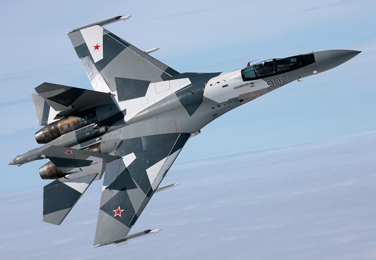
The L-band AESA
designed for embedding in the inboard leading edge of a fighter wing
was perhaps the most interesting single disclosure from the MAKS 2009
event in August, 2009. Tikhomirov NIIP's marketing material for this
product
describes it as intended for the “Su-27 (30) and Su-35 family of
aircraft” thus presenting it as a component for new
build aircraft and retrofit to existing fleet aircraft. Depicted the
second Su-35S prototype B/N 902 (KnAAPO image).
|
|
Abstract
Tikhomirov
NIIP
in
Moscow
are developing an L-band AESA radar system intended for
embedding in the leading edges of fighter wings. A demonstrator of the
L-band AESA subsystem was publicly displayed at MAKS2009.
This paper analyses the operational potential of this design, and
performs a range of performance estimates based on manufacturer
disclosures and known design features.
The design has clear
potential
to provide a genuine “shared
multifunction aperture” with applications including:
- Search, track and missile midcourse guidance against
low signature aircraft.
- Identification Friend Foe / Secondary Surveillance
Radar.
- Passive angle tracking and geolocation of
JTIDS/MIDS/Link-16 emitters at long ranges.
- Passive angle tracking and geolocation of L-band
AEW&C/AWACS and surface based search radars at long ranges.
- Passive angle tracking and geolocation of hostile
(i.e.
Western) IFF and SSR transponders at long ranges.
- High power active jamming of JTIDS/MIDS/Link-16
emitters.
- High power active jamming of satellite navigation
receivers
over large areas.
- High power active jamming of L-band AEW&C/AWACS
and
surface based search radars at long ranges.
- High power active jamming of guided munition command
datalinks over large areas.
Performance modelling for
a range of feasible configurations indicates
the radar will deliver tactically credible search range performance.
The Tikhomirov NIIP
L-band AESA is an important strategic
development, and a technology which, once fully matured and
deployed in useful numbers, will render narrowband stealth designs like
the F-35 Joint Strike Fighter and some UAVs, highly vulnerable to
Flanker variants equipped with such radars.
|
|
|
|
|
Introduction/Summary
Much of the media focus at the
MAKS 2009 event this August was directed at the X-band AESA design
produced by Tikhomirov NIIP, Russia's leading fighter radar house,
intended for use in the new T-50 / PAK-FA fighter and the T-10 /
Su-27/30/35 Flanker fighters.
Very little attention was paid to Tikhomirov NIIP's new L-band AESA
design, developed for embedding in the inboard leading edge flaps of
the T-10 / Su-27/30/35 Flanker fighter family. This is unfortunate, but
also not surprising, since Tikhomirov NIIP have disclosed very little
about the intended uses of this radar, and its intended
performance and capabilities.
The development of this radar has been discussed publicly in the
Russian technical press for some time now, but it has attracted very
little attention in the global defence debate.
The L-band, which in Russian usage typically refers to frequencies
between 1.0 GHz and 2.0 GHz, with wavelengths between 0.3 metres and
0.15 metres, is heavily populated with common services as well as being
a favoured band for long range search radars.
Services operating in the L-band include JTIDS/MIDS/Link-16, military
IFF and civil SSR transponders, Navstar GPS, Galileo and Glonass
satellite navigation, and a range of guided weapons datalinks. The band
is also used for some satellite communications uplinks and downlinks.
The NG MESA active array AEW&C/AWACS radar developed for the E-737
/ Wedgetail, the Israeli Elta EL/M-2075 Phalcon AESA radar used in the
Indian A-50I AEW&C/AWACS and the EL/W-2085 used in the G550 hosted
AEW&C aircraft, as well as the Chinese KJ-2000 and KJ-200
AEW&C/AWACS radars, all operate in the L-band. Russia's 59N6
Protivnik GE series and 67N6 Gamma DE AESA series long range mobile
search radars also operate in the L-band.
Why has the L-band been so popular? With operating wavelengths of the
order of 6 to 12 inches, it permits good long range search performance
with modestly sized antennas, while providing excellent weather
penetration, and reasonably well behaved ground clutter environments
compared to shorter wavelength bands. In airborne radar applications,
L-band offers an additional economy, as a single L-band design can
combine conventional primary radar functions with secondary IFF/SSR
functions, thus saving considerable antenna and transmitter/receiver
hardware weight, cooling and volume. The latter are alone sufficient
reasons to employ this otherwise heavily congested band.
Another less frequently discussed consideration is that L-band
frequencies typically sit below the design operating frequencies of
stealth shaping features in many fighter aircraft and UAV designs.
Shaping features such as engine inlet edges, exhaust nozzles, and other
details become ineffective at controlled scattering once their size is
comparable to that of the impinging radar waves. This problem is
exacerbated by the skin effect in resistive and magnetic materials,
which at these wavelengths often results in penetration depths
incompatible with thin coatings or shallow structures.
It was therefore
not surprising that during the 2000/2001 Australian media debate over
the Wedgetail AEW&C aircraft, US participants were quick to vocally
argue the “counter-stealth” capability of the Wedgetail's L-band
AESA radar design.
Recently performed Radar Cross Section modelling and
simulations
performed on key shaping features of the F-35 Joint Strike Fighter
show a pronounced degradation of shaping effects below the design's
optimal X-band operation.
Tikhomirov NIIP's uncharacteristic coyness about the intended uses of
the L-band AESA design has not precluded other program participants
from commenting. NPP Pulsar, who developed the RF transistor technology
used in the radar's TR modules, and the quad TR module design,
described the design as intended for “IFF, international SSR and search
radar functions”. For a dedicated IFF/SSR role, the Tikhomirov NIIP
L-band AESA would simply represent gross “overkill” in performance and
angular coverage, which is not characteristic of Russian design
philosophy, nearly always focussed on the full exploitation of the
technological potential of each design component.
The Pero PESA design developed by Tikhomirov NIIP for upgrades to
legacy Flanker N001V series radars is an interesting example, as it
combines a reflective X-band array for search functions, and an
embedded transmissive L-band array for IFF/SSR functions. The
“traditional” approach to IFF/SSR integration in both US and Russian
planar array MSAs has been to fit one or two rows of L-band dipoles on
the face of the antenna. Power aperture performance or angular accuracy
has tended not to be a high design priority in IFF/SSR applications, as
the targets are cooperative, and use active transponder beacons. Skin
return is not a
consideration in IFF/SSR application performance.
The volume, weight,
power, cooling and cost penalties of putting an L-band search radar on
a fighter have historically precluded the use of this band in fighter
applications. An X-band or Ku-band radar provides for greater accuracy,
and vastly better antenna directivity, given the available geometries
for installing radar antennas. The only reason to pursue the L-band is
thus if it can do something which cannot be done easily in the
X/Ku-bands. That something is inevitably the ability to produce useful
skin returns from targets which are difficult to detect and track in
the X/Ku-bands. Embedding an IFF/SSR function in the design simply
increases the design payoff, as a single design can perform two
functions, interleaving IFF/SSR interrogation messages with target
search pulse trains.
A high performance L-band AESA is not constrained in its basic usage to
supporting Counter-VLO search/track and IFF/SSR functions alone.
Because the L-band is used by so many disparate services, coverage of
this band opens up numerous other applications, once such an AESA has
been installed:
- Passive angle tracking and geolocation of
JTIDS/MIDS/Link-16 emitters at long ranges.
- Passive angle tracking and geolocation of L-band
AEW&C/AWACS and surface based search radars at long ranges.
- Passive angle tracking and geolocation of hostile (i.e.
Western) IFF and SSR transponders at long ranges.
- High power active jamming of JTIDS/MIDS/Link-16 emitters.
- High power active jamming of satellite navigation receivers
over large areas.
- High power active jamming of L-band AEW&C/AWACS and
surface based search radars at long ranges.
- High power active jamming of guided munition command
datalinks over large areas.
This is nothing less than the “shared multifunction aperture” model now
very popular in the design of Western X-band fighter radars, examples
including the Raytheon APG-79 and NG APG-81.
Many of these functions can be integrated into the design without great
difficulty, in part due to the modest number of antenna elements used
in an L-band design, and in part because the demands in digitising,
synthesizing, and processing lower band waveforms are much less
technically challenging
than in the X-band or Ku-band.
The Tikhomirov NIIP L-band AESA design is an important first step in
developing the full technological potential inherent in an L-band
multifunction aperture design, and once fully integrated and matured on
the Flanker airframe, this design is likely to be become the vehicle
for progressive incremental addition of further capabilities over time,
a deployment model increasingly popular in modern Russian designs, and
widely practiced in the West.
The effectiveness of the design in any of its intended or potential
roles will critically depend upon how well the AESA has been designed.
Power-aperture product performance will be especially important in
Counter-VLO search/track roles, and any active jamming roles.
Performance modelling for a range of feasible configurations indicates
this radar will deliver tactically credible search range performance.
Radiofrequency power output will not be a major technological problem
longer term, given the
increasing availability of Gallium Nitride commercial and military
radio-frequency power
transistor technology, and the size of the Flanker airframe which
permits the integration of effective liquid cooling systems without
great difficulty, a major design problem with smaller fighter designs.
Critics
who might choose to dismiss the importance of the Tikhomirov NIIP
L-band AESA should carefully consider the very significant performance
and growth
potential of such designs even in the short 2010 - 2015 timescale. NPP
Pulsar have been very active in Gallium Nitride technology with
numerous publications in Western research journals and conferences.
In summary, the Tikhomirov NIIP L-band AESA is an important strategic
development, and one which has the potential, once fully matured and
deployed in useful numbers, to render narrowband stealth designs like
the F-35 Joint Strike Fighter or some UAVs, highly
vulnerable to Flanker variants equipped with such radars. It is
a
classical case
study of lateral technological evolution, and smart technological
strategy, a game Russia's defence industry plays exceptionally well.
|
|
Design Philosophy - A Radar Engineering
Perspective
General layout of the
Tikhomirov NIIP L-band AESA radar antenna design, in the leading edge
flap of an Su-27 Flanker aircraft (Tikhomirov NIIP).
Performing an exact and
detailed technical analysis of any new radar design, in the absence of
detailed technical disclosures, always presents interesting challenges.
The L-band AESA is no exception in this respect, moreso since there are
no direct Western or Russian equivalents to compare it against.
Therefore any analysis must be performed from first principles, using
established design theory for antennas, AESA technology, and pulse
Doppler radar.
L-Band Array
Angular Coverage
The basic array design and integration into the leading edge flap
structure are well documented via a wealth of imagery produced at the
MAKS 2009 event. Each array employs twelve antenna elements. Three quad
TR modules each drive four antenna elements, for a total of twelve
elements per array, in three subarrays. The linear array is embedded in
the leading edge of
the wing flap, with the geometrical broadside direction normal to the
leading edge. The leading edge skin of the flap covering the AESA is a
dielectric radome which is conformal with the flap leading edge shape.

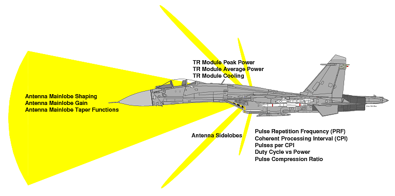
Figure 1: The array geometry produces a
fan shaped
mainlobe which is swept in azimuth by phase control of the
twelve TR modules, providing a 2D volume search capability (Author,
Flanker diagram Marco Falkenberg).
As the array is only one
element deep in height, the angular
coverage it provides in elevation will be fixed, and determined by the
vertical mainlobe shape of the antenna elements. The arrangement of the
AESA
produces a fan shaped beam which is swept in azimuth to cover a volume
in the forward hemisphere of the aircraft. Refer Figure 1.
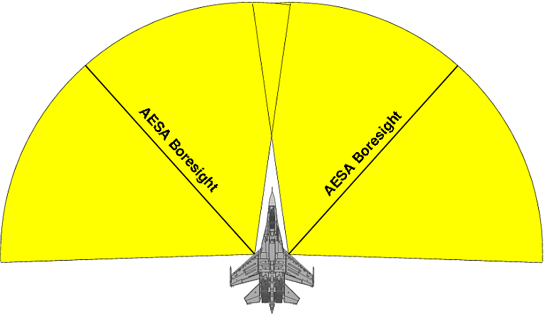
The achievable geometrical angular coverage in azimuth for the
placement of the AESA on the airframe is depicted in Figure 2.
Figure 2: AESA geometrical field of regard, assuming a mainlobe beam
steering
angle of ±50° off the array boresight. Single plane monopulse precision
angle tracking is feasible in the volume covered simultaneously by both
arrays (Author).
Whether the AESA can actually sweep the full volume which is
geometrically available depends primarily on the mainlobe shape and
boresight direction of the antenna elements, which has yet to be
disclosed. As the imagery of the antenna elements conceals the internal
structure under a dielectric cover, at best we can make reasonable
assumptions about the design.
The most likely technology employed is that of a microstrip antenna
with a dielectric foam or air gap spacer, forming a sandwiched block.
This technology has been used extensively in L-band designs for
communications and satellite navigation, as it affords precision
control
of characteristics and relatively low fabrication cost, with good
repeatability in production. This technology would also permit precise
shaping of the mainlobe in both axes and control of element sidelobes.
There is an inherent tradeoff in such a design. Elements with higher
gain will impose restrictions on bandwidth, and in beamsteering angle.
The latter is critical in this application, since wide beamsteering
angles in azimuth dictate a wide radiation pattern in azimuth. The
element mainlobe angular width must be greater than the maximum
beamsteering angle, or significant loss in total array gain will occur
as the AESA mainlobe is steered into the region where element gain
falls off rapidly with azimuth angle.
In operational terms, the AESA must be capable of sweeping the volume
in front of the aircraft's nose, either in IFF/SSR, search
or jamming applications. The physical alignment of the array is with
the leading
edge of the wing, at ~42° for the Flanker airframe.
This permits two possible design strategies for the antenna elements.
The first is to employ very low gain elements, with a mainlobe 3 dB
width in azimuth well in excess of the beamsteering angle required to
cover the nose region. This angle would be of the order of 55° to 65°,
beyond which grating lobe and other problems tend to be inevitable.
This design approach provides the best possible angular coverage,
effectively the full forward hemisphere. However, it also drives up the
emitted power requirement for any given detection range performance, as
the total array gain is reduced.
An alternate strategy is to sacrifice total angular coverage to
increase total array gain, and thus maximise power-aperture product
achieved for a given TR module power rating. If the AESA is intended to
provide significant detection performance operating as a radar, this is
the preferred strategy. Implementing this strategy requires some
trade-off between total beamsteering angular coverage of the array
versus the per-element gain. This will be discussed further.
Both design strategies permit single plane monopulse angle tracking
within a narrow angular volume around the nose of the aircraft, where a
target is within the coverage of both the left and right wing mounted
AESAs. This is an operationally acceptable arrangement as the precision
angle tracking provided by monopulse operation is employed primarily
for weapon targeting. This does not preclude performing single plane
monopulse angle tracking within each of the AESA arrays, using the
subarrays, but affords
higher total gain and detection range performance.
Provision of a 3D tracking capability is more difficult in the absence
of any vertically displaced antenna elements in the arrays. However, if
we assume that such a capability is only required for targets directly
in front of the aircraft to produce a fire control solution, two
options are available.
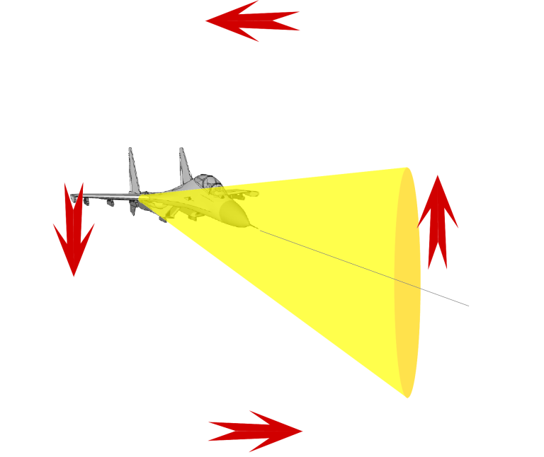
Figure 3: The cheapest solution
to the
provision of a heightfinding capability is to point the aircraft nose
at the target, and then perform an aileron roll manoeuvre while
tracking the target, with resulting height resolution similar to
azimuth resolution (Author,
Flanker diagram Marco Falkenberg).
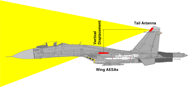
Figure 4: The more expensive but also more capable solution to the
provision of a heightfinding capability is to add additional antennas
on the vertical tails. This solution permits continuous height
measurement of targets within the coverage of these antennas (Author).
The cheaper option, with inherent limitations, is for the
aircraft to
fly an aileron roll manoeuvre whenever a height measurement of the
target is required. A full 360° roll sees the target position measured
through a full 2 π
angular extent, per manoeuvre. Whilst cheaper, this
approach is not suitable for continuous tracking, and could present
issues with clutter handling. Refer Figure 3.
The more expensive approach, which is suitable for continuous tracking,
is to add an additional high gain receive antenna suite, which is
vertically
displaced relative to the plane of the aircraft's wing, and thus the
AESA. Such an antenna could be integrated into the leading edge of one
or both of the vertical tails of the Flanker with no difficulty. Phase
alignment of the monopulse sum and difference signals produced by the
wing and tail arrays could be readily achieved by inserting a delay
line between the wing array outputs and the sum/differencing network.
Refer Figure 4.
As noted earlier, exact analysis of antenna performance and coverage
will have to await more detailed technical disclosures by the
manufacturers.
|
L-Band AESA
Components and Integration
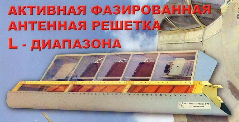
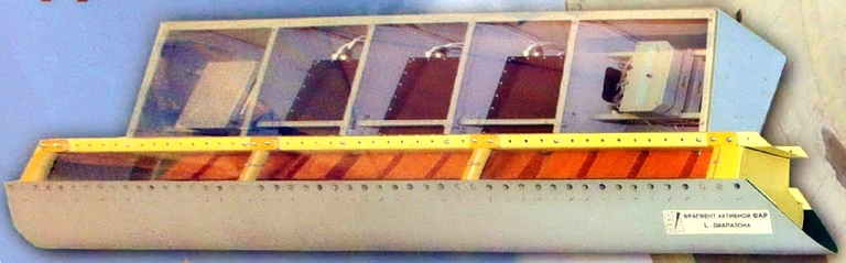 Figure L-band AESA general
layout
(Tikhomirov NIIP).
Figure L-band AESA general
layout
(Tikhomirov NIIP).
 L-band AESA leading edge flap
installation
on Su-30MK airframe (Tikhomirov NIIP).
L-band AESA leading edge flap
installation
on Su-30MK airframe (Tikhomirov NIIP).
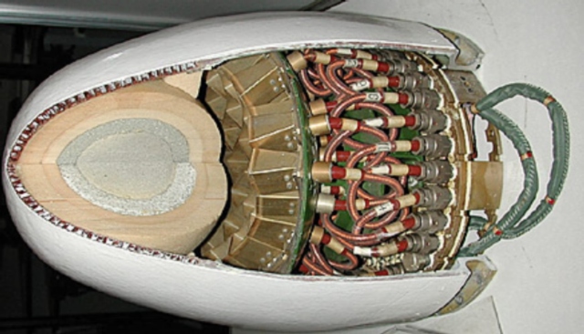
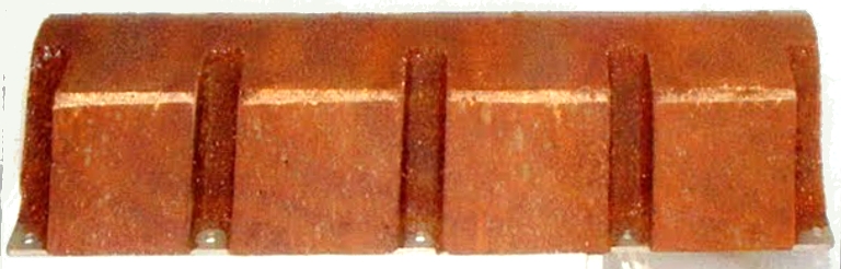 L-band AESA quad radiator
element subarray (Tikhomirov NIIP).
L-band AESA quad radiator
element subarray (Tikhomirov NIIP).
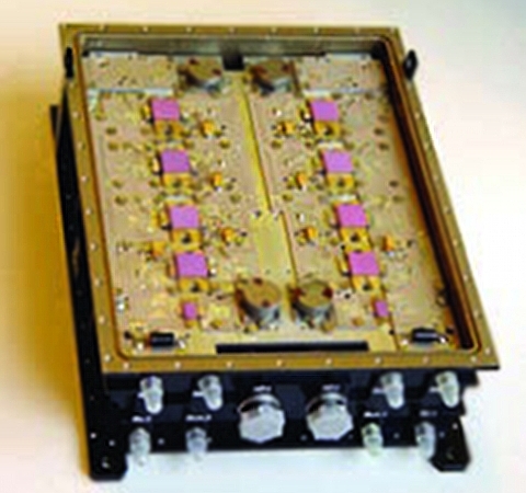
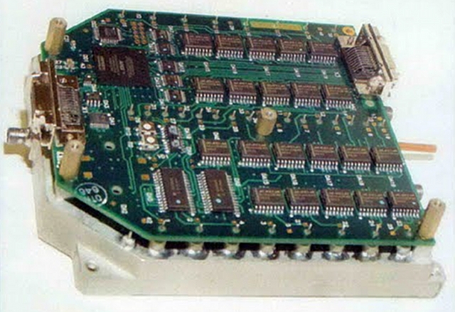
NPP
Pulsar quad high power L-band TR-module used in the L-band AESA design.
Note the use of eight RF power transistors in the design
(NPP Pulsar).
NIIP
antenna
control
module for the L-band AESA (Tikhomirov NIIP).
|
|
|
L-Band AESA
Performance Modelling and Growth Potential
The absence of exact performance characteristics for the antenna
element design
employed necessarily constrains any estimation of detection range
performance. This is compounded by the absence of any detailed
description of the intended radar waveform and other cardinal design
parameters. As a result all performance analyses must be based upon
reasonable assumptions about the design strategy intended, in turn
based upon reasonable assumptions of what performance and capabilities
might be required for the design to be effective.
To produce a representative performance estimate it is necessary, to a
large degree, to produce a basic radar design definition and
performance model which fits the parameters which are known.
The simplest strategy for NIIP to pursue in designing a pulse Doppler
radar RF and processing subsystem for the L-band AESA is to adapt an
existing design, an evolutionary model frequently used by Russian
designers. It is likely that the N035 Irbis E is being used for this
purpose with the new X-band AESA design. Once such a radar exists,
adapting it for use with an L-band AESA would involve only modest
engineering effort.
Longer term an operational design would likely emulate the US “Dual
Band
Radar” design strategy employed in the DDG-1000 weapon system, with
separate L-band and X-band AESAs, using separate optimised power
supplies and RF components, but sharing common central digital signal
processing and data processing subsystems. In an airborne application
where weight and volume are real problems, this is arguably the optimal
strategy.
NPP Pulsar, the manufacturer of the TR modules and transistors employed
in the modules, have made some most interesting disclosures which
are very helpful in assessing performance:
- TR module frequency band coverage between 1.0 and 1.5 GHz.
- TR module volumetric power density of 2 kiloWatts/litre.
- TR module nominal power rating of 200 Watts per TR channel,
for a
total of 2.4 kiloWatts per array, and 4.8 kiloWatts for a two array
installation.
These cited performance numbers need to be carefully qualified, as the
manufacturer has also elaborated on the design of their Silicon RF
power transistors intended for pulsed power applications such as
L-band and S-band TR modules.
| Table 1: Representative L-Band Transistor
Parameters |
Transistor
|
Rating
@
Duty
Cycle
|
Manufacturer
|
Notes
|
L-Band
BJT
|
250
W
@
10%
|
NPP
Pulsar
|
Used
by
T-NIIP
|
HVV1214-250L
|
250
W
@
10 %
|
HVVi
|
-
|
BLL6H1214-500
|
500
W
@
10%
|
NXP/Philips
|
LDMOS
|
IB1214M375
|
375W
@
10%
|
Integra
Technologies
|
BJT |
IBP1214M700
|
700W
@
10%
|
Integra
Technologies
|
Module
2
x
BJT
|
Source:
Manufacturers
|
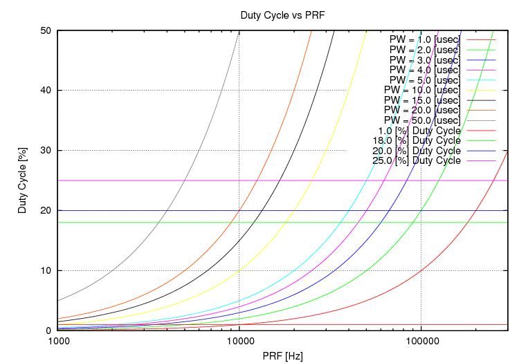
Specifically NPP Pulsar discuss the development of transistors rated to
deliver 500 Watts for 10 μsec pulse durations at 1% duty cycle, 250
Watts for 100 μsec at 10% duty cycle,
and 150 Watts for 500 μsec at 15% duty cycle. In practical terms this
transistor design produces pulse
energies of 0.005 Joules at 1% duty cycle, 0.025 Joules at 10% duty
cycle, and 0.075 Joules at 15% duty cycle, favouring high duty cycle
lower peak power operating regimes. In pulsed operation at 100 Watts, a
duty cycle of ~18% and pulse duration of ~700 μsec appear to be the
performance limits.
The company already manufactures 1.5 kiloWatt rated liquid cooled TR
modules for surface based radar applications, and solid state IFF/SSR
transmitters rated at 3 kiloWatts. A number of these designs employed
ganged transmitter stages, some with up to 64 solid state modules.
The current Tikhomirov NIIP L-band AESA design does not appear to use a
liquid cooling loop, given the absence of plumbing, and appears to
employ conduction cooling to the airframe metal structure instead. This
will inevitably limit the average power rating of the equipment, in
comparison with a liquid cooled design. The exposed TR module image
released by NPP Pulsar in late 2008 shows eight RF power transistors
driving four antenna elements, which is consistent with a pair of
transistors each driving 100 Watts into one element, with a maximum
sustained duty cycle of ~18% for the stated transistor performance.
For comparison, the liquid cooled solid state L-band TR modules
developed a
decade ago for the US NG MESA design were at the time cited at 1.0 -
1.5
kiloWatts per channel, whether the actual production design can deliver
this peak power rating remains to be disclosed.
With the existing Tikhomirov NIIP L-band AESA design using twelve TR
channels per array, and a pair of arrays, the NPP Pulsar disclosure
permits some estimation of nett AESA power ratings. The lower bound on
the design is 2 x 12 x 200 Watts, for a total peak rating of 4.8
kiloWatts,
with a duty cycle of ~18% and maximum pulse duration under 800 μsec.
The design is likely operated in C class, although some cited Russian
designs use
A class or quasi-complementary AB class circuits.
If we then assume each TR channel can produce one kiloWatt of RF power
with
more powerful ganged RF transistors with a total rating of 500 Watt /
~20% Duty Cycle,
then this yields a rating of 2 x
12 x 1 kiloWatt for a total of 24 kiloWatts for a pair of arrays. The
latter will require liquid cooling at any significant duty cycle. Table
1 shows examples of a number of representative L-band power
transistors available commercially at this time.
In
comparison with X-band fighter AESAs, these are excellent numbers, but
for an L-band AESA with a factor of ten or more lower antenna gain, are
not necessarily stellar.
The nett gain achievable by the each array element will depend strongly
on the intended tradeoff between azimuthal angular coverage versus
gain, but also upon the elevation coverage intended. For typical
geometries of interest in air combat between fighter aircraft, an
elevation coverage of +5° to -15° would permit acquisition of most
targets of interest, resulting in a mainlobe width in elevation of ~20°.
From an antenna design perspective, narrowing the mainlobe in elevation
is a modestly challenging task. Design options include changing the
aspect ratio of the microstrip radiating element, or introducing a graded dielectric
lens element in front of microstrip element, the
latter approach used in existing Russian electronic warfare equipment
for phased array mainlobe shaping.
Several estimations of element gain can be applied. The first is the
simple rule of thumb estimate of ~6 dBi per element. If we assume a
more refined design, with a mainlobe of 80° in azimuth and 40° in
elevation, and apply Barton's approximation, G = 30,000/(θaz
x θel), the element gain is ~9.7 dBi. Finally, we might
assume a dielectric lens or more aggressive microstrip design, or some
combination thereof, with an mainlobe size in elevation of 20°, which
yields, again using Barton's approximation, an element gain of ~13 dBi.
Sidelobe performance will be poor compared to X-band AESAs, due to the
limitations inherent in a 12 x 1 element linear array. While an
aggressive taper function could be applied, the low element count
precludes very low sidelobe performance, even with concurrent element
gain and phase control.
Receiver noise figure performance for the L-band AESA should be
excellent, due to the short feed between the TR module and antenna
element, the potential for low loss integral directional coupler
design, and typical transistor noise figures in the L-band of a small
fraction of a dB. The effective noise figure is likely to be dominated
by losses between the antenna and transistor, and of the order of 1 dB.
Overall system noise temperature will be dominated by antenna noise
produced by the environment.
What choices in PRF, CPI, duty cycles and pulse compression technique
Tikhomirov NIIP will opt for remains to be seen. Little has been
disclosed on existing X-band designs to date, although public
disclosures suggest that Barker codes may be in use for pulse
compression.
Open source data indicates that most operating modes in Russian pulse
Doppler designs emulate those commonly used in US designs, with medium
and high PRF modes commonly used. At least one Russian design is known
to interleave medium PRF and high PRF regimes to maximise performance
against concurrent mixes of closing and receding targets.
Detection range performance in coherent pulse Doppler designs depends
strongly
on power-aperture product, but also on coherent integration time,
PRF, duty cycle. Representative
instances for typical radars summarised by Lynch (Skolnik 3rd Ed, 2008)
were employed as cardinal parameters for modelling this design.
If the intent of the design is to maximise detection range against
closing low signature targets, then the design imperative will be to
maximise the emitted energy per dwell, and minimise the noise
bandwidth. This usually leads to the choice of a High PRF regime
Velocity Search (VS) or Range Gated High PRF Range While Search (RWS)
regime, or some interleaved combination of the two, with a maximum
coherent integration time duration to maximise the coherent integration
gain.
While X-band radars have HPRF regimes at 100 kHz to 300 kHz, an L-band
design will exhibit similar unambiguous Doppler at much lower PRFs, of
the order of 25 kHz to 75 kHz, due to the four to six times lower
operating
frequency (Stimson 1998).
In the cardinal co-altitude air to air engagement geometry for closing
high speed targets at medium to high altitudes, the target Doppler will
be well outside Mainlobe Clutter (MLC) and Sidelobe Clutter (SLC) which
simplifies analysis. As the radar scans only in azimuth, the available
dwell time per angle can be greater than in a comparable X-band search
radar mode, thus minimising the dB loss incurred due to beamshape and
scan considerations, another simplification to the model.
A key consideration in such a regime of operation is that of how many
pulses can be coherently integrated. This will be limited by the
coherence length/time of the master oscillator employed, a parameter
the Russians have not disclosed for any recent radar designs, and the
Doppler filter bandwidth which is readily estimated.
Noncoherent integration incurs up to several dB of loss in the
integration of large pulse trains.
Table 3 provides some coarse detection range performance estimates,
based on parameters in Table 2.
|
Table 2: Pulse Doppler Baseline Performance
Model Parameters
|
Parameter
|
Values
|
Notes
|
Frequency
f0 [GHz]
|
1.25
|
NPP
Pulsar
spec |
Wavelength
λ [m]
|
0.24
|
NPP
Pulsar
spec |
Operating
Mode
|
HPRF
VS/RWS
|
Preferred
modes
long
range detection; CBDR outside MLC, SLC
|
Duty
Cycle,
Max
[%]
|
18.0
|
NPP
Pulsar
spec
|
Pulse
Power
- Ppeak [kW]
|
4.8
|
NPP
Pulsar
TR
module @ 18.0 % D.C.
|
Average
Power
- Pave [kW]
|
0.864
|
Given
18.0
%
D.C.
|
Dwell
Time
[sec]
|
0.1
|
Narrow
sector
search;
azimuth only; both arrays
|
BWDoppler
[Hz]
|
20
Hz
|
Filter
BW
[NB f0 = 1.25 GHz]
|
CPI [sec]
|
0.05
|
Multiple
PRFs
per
dwell |
| Tpulse
[μsec] / PRF [Hz] / Nc
[-] |
N/A
|
Nc
= Pulses / CPI
|
Lb
[dB]
|
0
|
Beamshape
Loss
[NB
assume stabilised AESA long dwell]
|
Lsc
[dB]
|
0
|
Scan
Loss [NB assume stabilised AESA long dwell] |
| Lst
[dB] |
3
|
Straddling
Loss
|
| Li
[dB] |
4
|
Integration
Loss
|
| Le
[dB] |
0
|
Eclipsing
Loss
[NB
Assume VS mode]
|
| F [dB] |
4
|
Fluctuation
Loss
|
Ts
[K]
|
400
|
System
noise
temperature
|
| SNRreq [dB] |
11.0
|
Required
SNR
for Pd =
0.9;
assume
mode interleaving, alert/confirm
|
|
Table 3: Range for 1 m2 Target vs. Modelled L-Band AESA
Configurations
|
Antenna/TR
Module
|
Gain/Side
[dBi]
|
Pave
[kW/dBW] |
R
@
1
m2 [km/NMI]
|
Notes
|
2
x
12
Baseline / Baseline
|
20.5
|
0.864
/
29.4
|
73.3
/
39.6
|
9.7
dBi/element
|
2
x
12
Hi Gain / Baseline
|
23.8
|
0.864
/
29.4
|
89.1
/
48.1 |
13
dBi/element |
2
x
12
Baseline / Uprated
|
20.5
|
2.16
/
33.3
|
91.2
/
49.2 |
9.7
dBi/element |
| 2
x
12
Hi Gain / Uprated |
23.8
|
2.16
/
33.3
|
110.9
/
59.9 |
13
dBi/element |
| 2
x
16 Baseline / Uprated |
22.2
|
2.88
/
34.6
|
109.0
/
58.8 |
9.7
dBi/element |
| 2
x
16
Hi Gain / Uprated |
25.1
|
2.88
/
34.6
|
128.8
/
69.6 |
13
dBi/element |
Notes/Assumptions:
- 18% Duty Cycle; growth variants may employ
much higher Duty Cycles;
- Add 3 dBi for paired arrays;
- Range model as per Skolnik 3E 4.16 with
assumed low loss coherent integration;
- All ranges for target RCS of 1 m2
in L-band;
- Configurations with uprated TR modules assume
500 W peak rated transistors at like duty cycle.
- The model is based upon a series of reasonable
assumptions about the radar design, but in the absence of hard design
parameters disclosed by Tikhomirov NIIP, these are only assumptions -
the actual performance of radar could be considerably better or worse
depending on specific design choices and implementation constraints,
including factors such as the absence or presence of STAP processing,
and choices in FAR, Pd, and other cardinal
parameters.
|
|
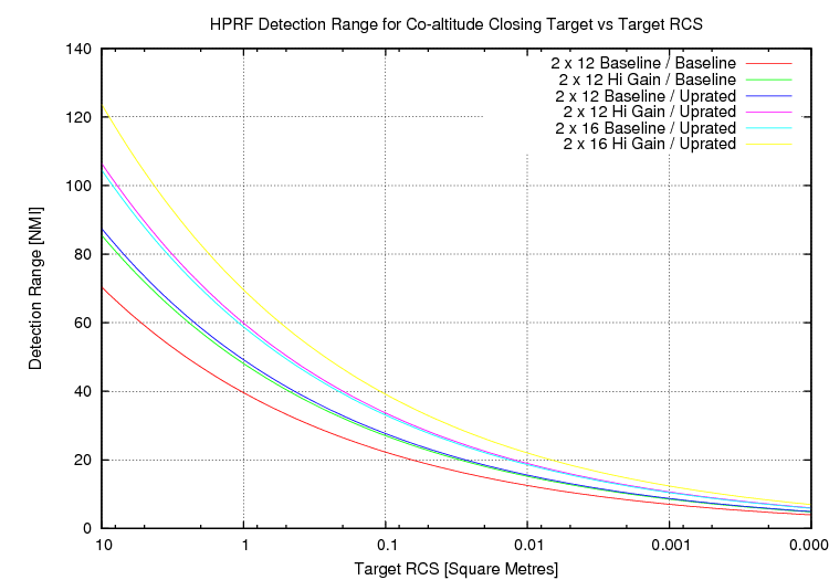
Detection range in nautical
miles, RCS in square metres.
Modelling of the radar's
performance for a range of viable configurations shows detection range
performance against 1 m2 class target to be tactically
credible, especially for configurations with higher gain antenna
modules and higher TR module average power ratings. This analysis
is inherently limited by the poor availability of data covering the
actual design, especially in terms of coherent processing parameters
and other basic choices. By increasing dwell times and coherent
processing interval durations, range performance could be further
improved in this regime.
|
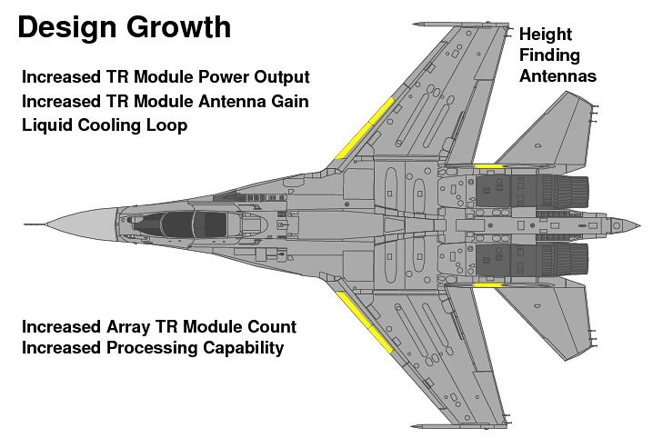
The Tikhomirov NIIP L-band AESA has considerable growth potential by
virtue of the large size of the Flanker airframe, permitting additional
antenna elements, cooling and power.
Growth options include:
- Increasing the power rating of the existing TR modules,
retaining conduction cooling.
- Further increasing the power rating of the TR modules and
introducing liquid cooling.
- Improvements to antenna element design to increase element
gain.
- Extending the arrays further along the wings, to add an
additional one or two subarrays.
- Addition of receiver arrays in the leading edge of the
vertical tails to provide dual plane monopulse precision angle tracking
capability for fire control purposes.
For instance, increasing the array size to 16 elements improves
power-aperture product for the existing design by almost 80%, by virtue
of additional gain and transmit power. The use of more powerful TR
modules provides for further improvements. The practical limit will be
the available leading edge flap volume as the design progressively
tapers toward the
wingtips, and system constrains on liquid cooling capacity.
|
Acknowledgments
The author is indebted to all
parties in Australia and overseas who
reviewed the draft of this
paper, for their cogent comments and input. Thanks also to Dr Nemai
Karmakar of Monash University, for his most helpful advice on the
design of microstrip antenna elements for active phased arrays, an area
he has specialised in for nearly twenty years.
|
Bibliography/References
- Stimson
G.W., Introduction to Airborne Radar,
2nd
Edition Scitech Publishing, 1998 (highly recommended).
- Skolnik
M.I. (Editor), Radar
Handbook
3rd
Edition, 007057913X,
McGraw-Hill, February, 2008 (highly recommended).
- Bassem R. Mahafza, Introduction
to Radar Analysis, CRC Press, ISBN 0849318793.
- Knott E.F., Schaeffer J.F. and
Tuley M.T., Radar Cross Section,
First
Edition,
Artech House, 1986.
- Knott E.F., Schaeffer J.F. and
Tuley M.T., Radar Cross Section,
Second
Edition,
Artech House, 1993 (highly recommended).
- Fred E. Nathanson, J. Patrick
Reilly, Marvin N. Cohen, Radar
design principles: signal processing and the environment, Second
Ed, Scitech Pub., Mendham, NJ, 1999.
- Karmakar, N.C.
Bialkowski, M.E., Circularly polarized aperture-coupled circular
microstrip patch antennas for L-band applications, IEEE Transactions on Antennas and
Propagation, Volume: 47, Issue: 5, IEEE, May 1999.
- В.Аронов, А.А.Евстигнеев,
А.С.Евстигнеев, «Транзисторные
передающие модули L- и S- диапазонов», Электроника:НТБ, ЗАО РИЦ
«Техносфера», URI: http://www.electronics.ru/pdf/4_2005/05.pdf
- А.Васильев, «Интегрированная база СВЧ-, силовой и
фотоэлектроники, НПП "Пульсар" в борьбе за рынок высоких технологий»,
Электроника:НТБ, ЗАО
РИЦ
«Техносфера», URI: http://www.electronics.ru/pdf/3_2008/1782.pdf
- L-band Active Phased
Array for Airborne Radars, technical brochure, V. Tikhomirov
scientific research institute of instrument design (NIIP), Address: 3,
Gagarina St., Zhukovsky, Russia 140181
- ОАО "НИИП им. В.В.
Тихомирова", Россия, 140181, г.Жуковский, ул.Гагарина, д.3
- Irkut
SPC (JSC),
125315, 68, Bldg. 1, Leningradsky prospekt, Moscow, 125315, Russia
- KnAAPO
(JSC),
ul.
Sovetskaya, 1, Komsomolsk-on-Amur,
681018, Russia
- Фотогалерея
первого
построенного
на КнААПО Су-35 (Imagery of first Su-35)
- Буклет
Су-35, архив с
буклетом в формате Adobe Reader.(Booklet Su-35)
- Презентационное
видео
о
Су-35.(Su-35 presentation)
- Основные
характеристики Су-35. Видео (Su-35 features - video)
- Sukhoi
Company (JSC), 23B, Polikarpov str.,Moscow, 125284,
Russia, p/b 604
- Su-35.
Multirole Super-Maneuverable Fighter. The Booklet. KNAAPO/Sukhoi
brochure (16 MB)
- Australian
Aviation - June
2002 - Active
Electronically
Steered
Arrays - A
Maturing
Technology
(Images Rosoboronexport,
RuMoD, Tikhomirov NIIP, KnAAPO, Other, Author)
|
|
Air Power Australia
Analyses ISSN 1832-2433
|
|
![Australia's First Online Journal Covering Air Power Issues [ISSN 1832-2433]](APA/APA-Title-Analyses.png "Australia's First Online Journal Covering Air Power Issues [ISSN 1832-2433]")


 [Click for more ...]")


