|
||||||||||||||||||||||
![Australia's First Online Journal Covering Air Power Issues [ISSN 1832-2433]](APA/APA-Title-Analyses.png "Australia's First Online Journal Covering Air Power Issues [ISSN 1832-2433]") |
||||||||||||||||||||||
 |
 |
 |
 |
 |
 |
 |
 |
|||||||||||||||
 |
 |
 |

|
 |
 |
 |
 |
|||||||||||||||
| Last Updated: Mon Jan 27 11:18:09 UTC 2014 | ||||||||||||||||||||||
|
||||||||||||||||||||||


| A
Preliminary
Assessment
of
Specular
Radar
Cross
Section
Performance
in
the
Chengdu
J-20
Prototype
Air Power Australia Analysis 2011-03 4th July 2011 |
||||||||||||||||||||||||||||||||||||||||||||||||||||||||||||||||||||||||||||||||||||||||||||||||||||||||||||||||||||||||||||||||||||||||||||||||||||||||||||||||||||||||||||||||||||||||||||||||||||||||||||||||||||||||||||||||||||||||||||||||||||||||||||||||||||||||||||||||||||||||||||||||||||||||||||||||||||||||||||||||||||||||||||||||||||||||||||||||||||||||||||||||||||||||||||||||||||||||||||||||||||||||||||||||||||||||||||||||||||||||||||||||||||||||||||||||||||||||||||||||||||||||||||||||||||||||
| A
Monograph
by Dr Michael J Pelosi, MBA, MPA, Dr Carlo Kopp, SMAIAA, SMIEEE, PEng Text, computer graphics © 2011 Michael Pelosi, © 2011 Carlo Kopp |
||||||||||||||||||||||||||||||||||||||||||||||||||||||||||||||||||||||||||||||||||||||||||||||||||||||||||||||||||||||||||||||||||||||||||||||||||||||||||||||||||||||||||||||||||||||||||||||||||||||||||||||||||||||||||||||||||||||||||||||||||||||||||||||||||||||||||||||||||||||||||||||||||||||||||||||||||||||||||||||||||||||||||||||||||||||||||||||||||||||||||||||||||||||||||||||||||||||||||||||||||||||||||||||||||||||||||||||||||||||||||||||||||||||||||||||||||||||||||||||||||||||||||||||||||||||||
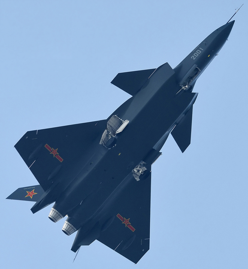
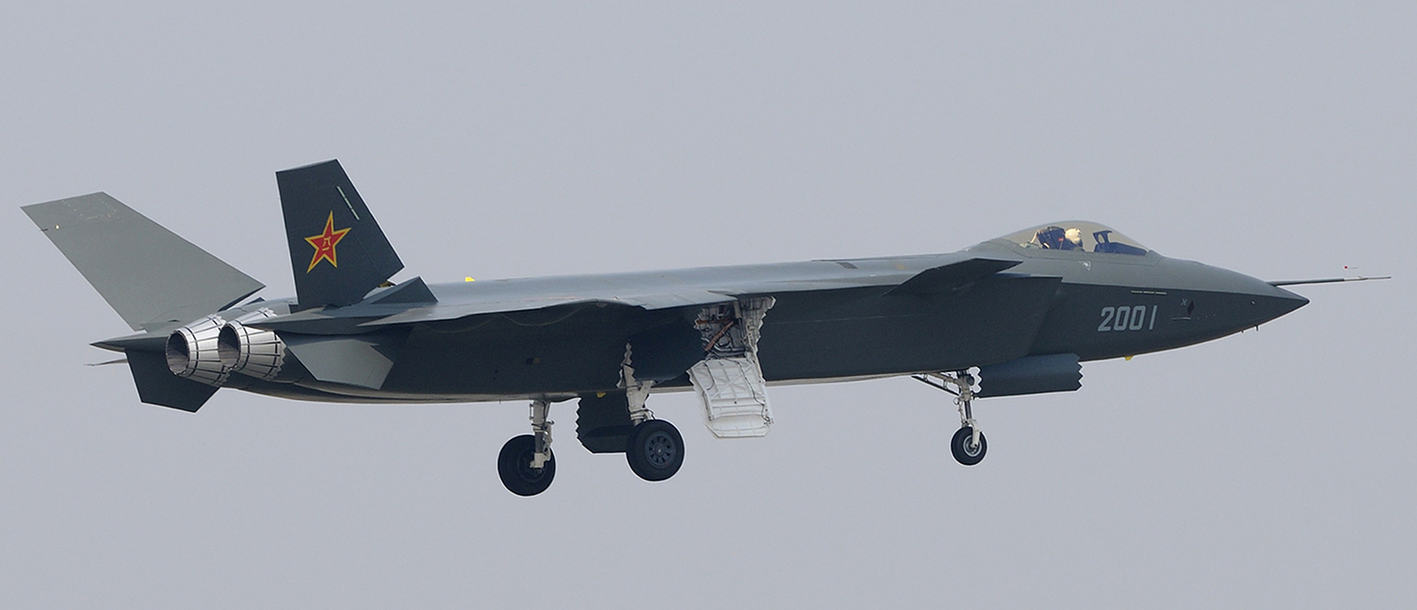 First public flight of the Chengdu
J-20
prototype, 11th January, 2011 [click to enlarge]. The shaping design of
the J-20 presents no fundamental obstacles to its development into
a genuine Very Low Observable design
(Chinese Internet).
|
||||||||||||||||||||||||||||||||||||||||||||||||||||||||||||||||||||||||||||||||||||||||||||||||||||||||||||||||||||||||||||||||||||||||||||||||||||||||||||||||||||||||||||||||||||||||||||||||||||||||||||||||||||||||||||||||||||||||||||||||||||||||||||||||||||||||||||||||||||||||||||||||||||||||||||||||||||||||||||||||||||||||||||||||||||||||||||||||||||||||||||||||||||||||||||||||||||||||||||||||||||||||||||||||||||||||||||||||||||||||||||||||||||||||||||||||||||||||||||||||||||||||||||||||||||||||
|
|
||||||||||||||||||||||||||||||||||||||||||||||||||||||||||||||||||||||||||||||||||||||||||||||||||||||||||||||||||||||||||||||||||||||||||||||||||||||||||||||||||||||||||||||||||||||||||||||||||||||||||||||||||||||||||||||||||||||||||||||||||||||||||||||||||||||||||||||||||||||||||||||||||||||||||||||||||||||||||||||||||||||||||||||||||||||||||||||||||||||||||||||||||||||||||||||||||||||||||||||||||||||||||||||||||||||||||||||||||||||||||||||||||||||||||||||||||||||||||||||||||||||||||||||||||||||||
|
||||||||||||||||||||||||||||||||||||||||||||||||||||||||||||||||||||||||||||||||||||||||||||||||||||||||||||||||||||||||||||||||||||||||||||||||||||||||||||||||||||||||||||||||||||||||||||||||||||||||||||||||||||||||||||||||||||||||||||||||||||||||||||||||||||||||||||||||||||||||||||||||||||||||||||||||||||||||||||||||||||||||||||||||||||||||||||||||||||||||||||||||||||||||||||||||||||||||||||||||||||||||||||||||||||||||||||||||||||||||||||||||||||||||||||||||||||||||||||||||||||||||||||||||||||||||
IntroductionThere has been extensive media speculation about the Radar Cross Section [RCS] of the J-20 stealth fighter, since the PLA-AF first exposed the prototype to the public in late December, 20104. Sadly much of this speculation has no valid scientific basis, yet appears to be regarded seriously enough to have influenced public statements by numerous senior officials in Western defence departments. Performing a full assessment of the RCS of any Low Observable [LO / -10 to -30 dBSM, Refer Table A.1] or Very Low Observable [VLO / -30 to -40 dBSM, Refer Table A.1] aircraft is not a trivial task, as due consideration needs to be given to all major and minor RCS contributors in the design. Moreover, such an assessment, if it is to be useful, must consider the RCS from a range of different angular aspects, this encompassing azimuthal sectors and also elevation or depression angles characteristic of the surface and airborne threat systems the LO/VLO design is intended to defeat [Refer Figures A.3 and A.4]. The assessment of RCS must also be performed at the operating wavelengths typical of the surface and airborne threat systems the LO/VLO design is intended to defeat [Refer Table A.2]. Definitions of these and other terms employed in this document are summarised in Annex E. Reference data for RCS scales, radio-frequency bands, engagement geometries, and representative threat systems are summarised in Annex A. If the RCS assessment does not consider angular and wavelength dependencies properly, it will be almost meaningless, in terms of providing a means of determining or estimating the survivability of the LO/VLO design. The common practice of providing a single RCS value for a single aspect at a single frequency yields little information about the actual effectiveness of the design. Such a single point figure permits at best a detection range estimate for a known radar operating at the specified wavelength and aspect. The PLA's J-20 prototype is an important development in terms of grand strategy, as well as technological strategy, and basic technology. It shows that PLA thinking at the strategic level is focussed on defeating opposing IADS [Integrated Air Defence System] and fighter forces. In the domain of technological strategy, it shows a robust grasp of the limitations of Western technology deployed in Asia. In terms of basic technology, it shows that China's academic research and industrial base has mastered advanced LO/VLO shaping techniques. The intent of this study is to perform a preliminary assessment of the RCS of the J-20 prototype, to establish the potential of the aircraft to be fully developed as an LO/VLO combat asset. The assessment cannot be more than preliminary for a number of good reasons:
The relative importance of the respective categories should be discussed. Sound airframe shaping is a necessary prerequisite for good LO or VLO performance. If shaping is poor, no amount of credible materials application and detail flare spot reduction will overcome the RCS contributions produced by the airframe shape, and genuine VLO performance will be unattainable. If airframe shaping is sound, then careful and well considered application of Radar Absorbent Materials (RAM), Radar Absorbent Structures (RAS), radar absorbent coatings, aperture RCS reductions, and minor flare spot reductions techniques will yield a VLO design. As a result, modelling of the shape related RCS contributions of any VLO design is of very high value, as it determines not only whether the aircraft can achieve credible VLO category performance, but also where the designers will be investing effort in RAS, RAM and coating application to achieve this effect. This paper will focus mostly on shape related RCS contributions, due to the uncertainties inherent in estimating the performance of unknown technologies for RAS, RAM, coatings, aperture RCS reductions, and minor flare spot reduction. Where applicable, reasonable assumptions will be made as to the performance of absorbent material related RCS reduction measures. Some tentative modelling of published Chinese RAM coatings will be performed. |
||||||||||||||||||||||||||||||||||||||||||||||||||||||||||||||||||||||||||||||||||||||||||||||||||||||||||||||||||||||||||||||||||||||||||||||||||||||||||||||||||||||||||||||||||||||||||||||||||||||||||||||||||||||||||||||||||||||||||||||||||||||||||||||||||||||||||||||||||||||||||||||||||||||||||||||||||||||||||||||||||||||||||||||||||||||||||||||||||||||||||||||||||||||||||||||||||||||||||||||||||||||||||||||||||||||||||||||||||||||||||||||||||||||||||||||||||||||||||||||||||||||||||||||||||||||||
J-20 Prototype Very Low Observable Airframe Shaping Design FeaturesThe J-20 prototype designs displays a number of VLO design features, generally based on design rules developed for and employed in the construction of United States VLO combat aircraft. These display a good theoretical and practical understanding of the VLO design rules developed by US researchers in industry and US government research laboratories, between 1975 and 2000. Overall, the stealth shaping of the J-20 prototype design is without doubt considerably better than that seen in the Russian T-50 PAK-FA prototypes and, even more so, than that seen in the intended production configuration of the United States' F-35 Joint Strike Fighter2,3. The J-20 design appears to be mostly constructed around the stealth shaping design rules employed in the US Air Force F-22A Raptor4:
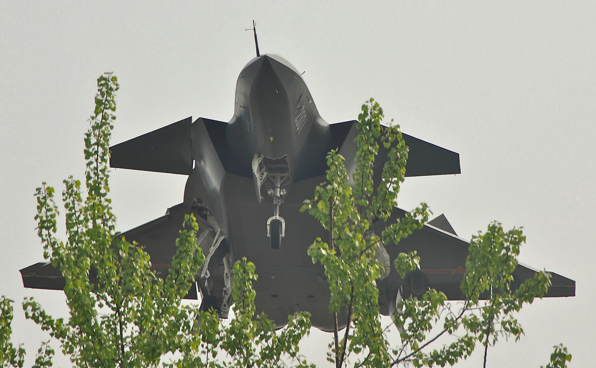
Available imagery from similar or identical aspects permits direct comparisons between the J-20 and the United States F-22A and F-35 designs.  Elevated head on view of J-20
prototype showing the
trapezoidal edge aligned inlet geometry, combining features of the
F-22A Raptor and F-35 JSF inlet. Both aircraft share shallow
wing/fuselage join angles and a flat lower fuselage (Chinese Internet).
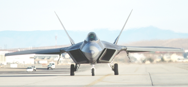 Head on view of F-22A Raptor
showing the
trapezoidal edge aligned inlet geometry (US Air Force).
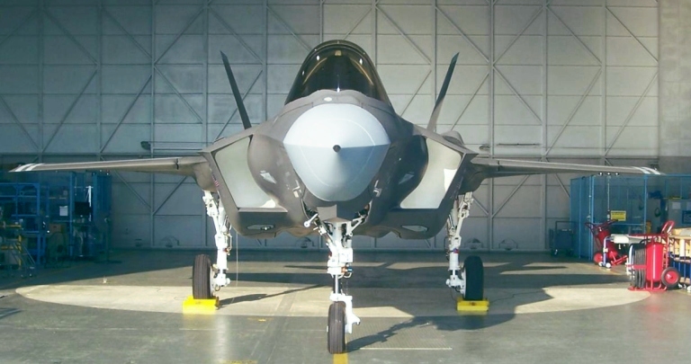 The shaping features of the inlet area and unique lower fuselage are prominent on this image of F-35A SDD prototype AA-1 (Image via Air Force Link).  This J-20 view shows the chine geometry, and generous use of X-band serrations on the undercarriage doors (Chinese Internet).  Ventral view of F-22A Raptor with
undercarriage extended (US Air Force).
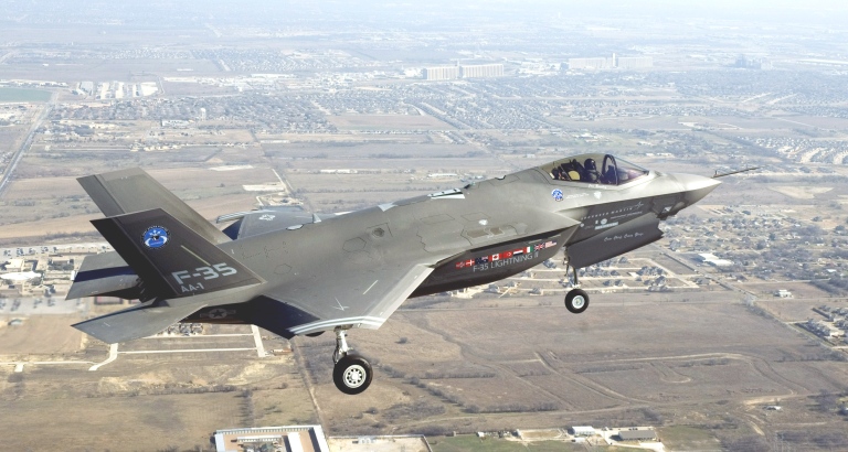 F-35 JSF SDD airframe in flight
showing
chine angles and upper fuselage curvature (U.S. Air
Force photo).
 Ventral view of J-20 prototype showing the flat lower fuselage, flat facet fuselage sides, and shallow join angle between the wings, canards and fuselage sides. The aft ventral strakes are undesirable from an RCS perspective (Chinese Internet). 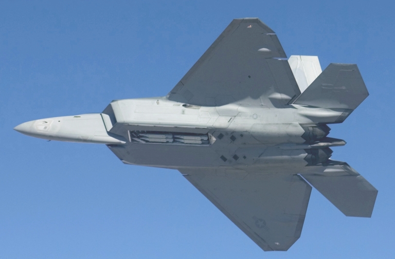 Ventral view of F-22A Raptor showing the flat lower fuselage, flat facet fuselage sides, and shallow join angle between the wings, horizontal tails and fuselage sides (U.S. Air Force photo).  Ventral view of F-35A SDD aircraft showing the deeply sculpted lower fuselage, doubly curved fuselage sides, and steep angle multiple step join between the wings and fuselage sides (U.S. Air Force photo).  Aft view of J-20 prototype showing the serrated axi-symmetric nozzles, modelled on the F-35 JSF design, the strakes and all moving tails, and deflected canards (Chinese Internet). 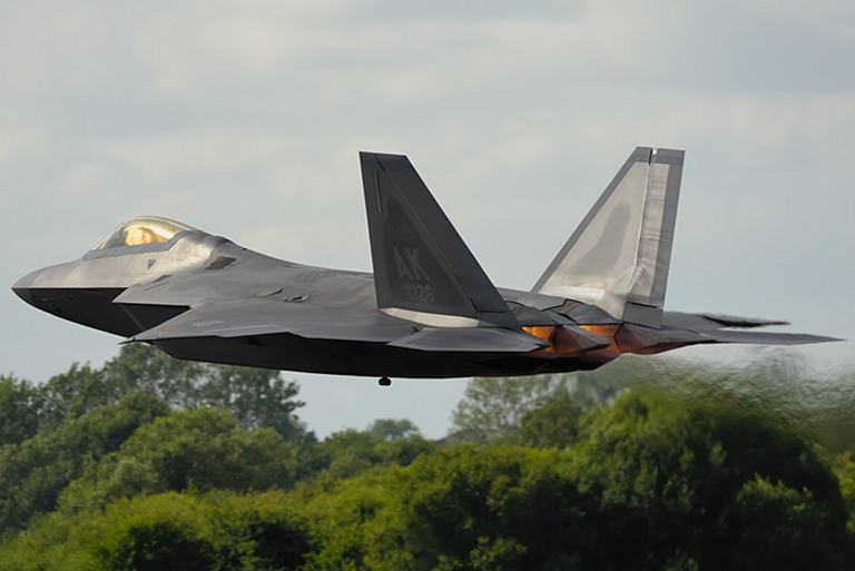 Forward ventral view of J-20 prototype showing the flat lower fuselage, flat facet fuselage sides, and shallow join angle between the wings, canards and fuselage sides. Note the detail of the inlet geometry (Chinese Internet). 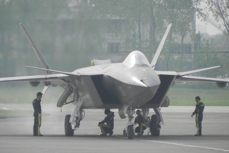 Near head on view of J-20 prototype showing the trapezoidal edge aligned inlet geometry , wing/fuselage join, and flat lower fuselage (Chinese Internet). 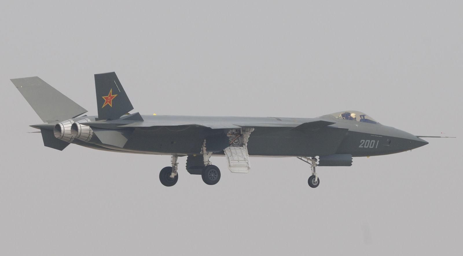 Rear quarter view of J-20
prototype showing the
axi-symmetric nozzles and strakes (Chinese Internet).
|
||||||||||||||||||||||||||||||||||||||||||||||||||||||||||||||||||||||||||||||||||||||||||||||||||||||||||||||||||||||||||||||||||||||||||||||||||||||||||||||||||||||||||||||||||||||||||||||||||||||||||||||||||||||||||||||||||||||||||||||||||||||||||||||||||||||||||||||||||||||||||||||||||||||||||||||||||||||||||||||||||||||||||||||||||||||||||||||||||||||||||||||||||||||||||||||||||||||||||||||||||||||||||||||||||||||||||||||||||||||||||||||||||||||||||||||||||||||||||||||||||||||||||||||||||||||||
Chinese
Absorbent Materials Technology
|
||||||||||||||||||||||||||||||||||||||||||||||||||||||||||||||||||||||||||||||||||||||||||||||||||||||||||||||||||||||||||||||||||||||||||||||||||||||||||||||||||||||||||||||||||||||||||||||||||||||||||||||||||||||||||||||||||||||||||||||||||||||||||||||||||||||||||||||||||||||||||||||||||||||||||||||||||||||||||||||||||||||||||||||||||||||||||||||||||||||||||||||||||||||||||||||||||||||||||||||||||||||||||||||||||||||||||||||||||||||||||||||||||||||||||||||||||||||||||||||||||||||||||||||||||||||||
Radar
Cross Section Simulation Method / Simulator Design and Capabilities
|
||||||||||||||||||||||||||||||||||||||||||||||||||||||||||||||||||||||||||||||||||||||||||||||||||||||||||||||||||||||||||||||||||||||||||||||||||||||||||||||||||||||||||||||||||||||||||||||||||||||||||||||||||||||||||||||||||||||||||||||||||||||||||||||||||||||||||||||||||||||||||||||||||||||||||||||||||||||||||||||||||||||||||||||||||||||||||||||||||||||||||||||||||||||||||||||||||||||||||||||||||||||||||||||||||||||||||||||||||||||||||||||||||||||||||||||||||||||||||||||||||||||||||||||||||||||||
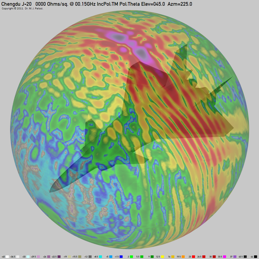
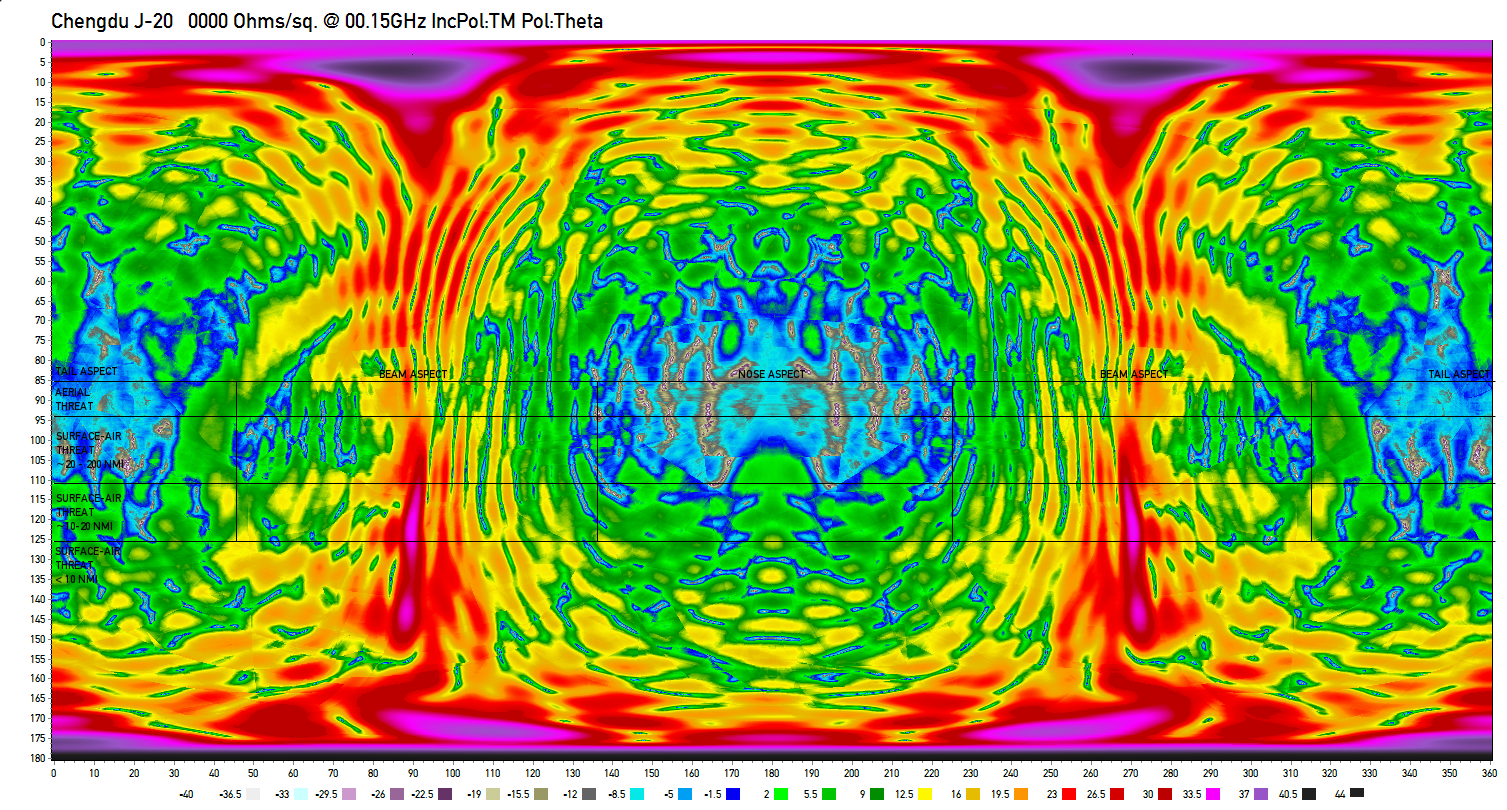
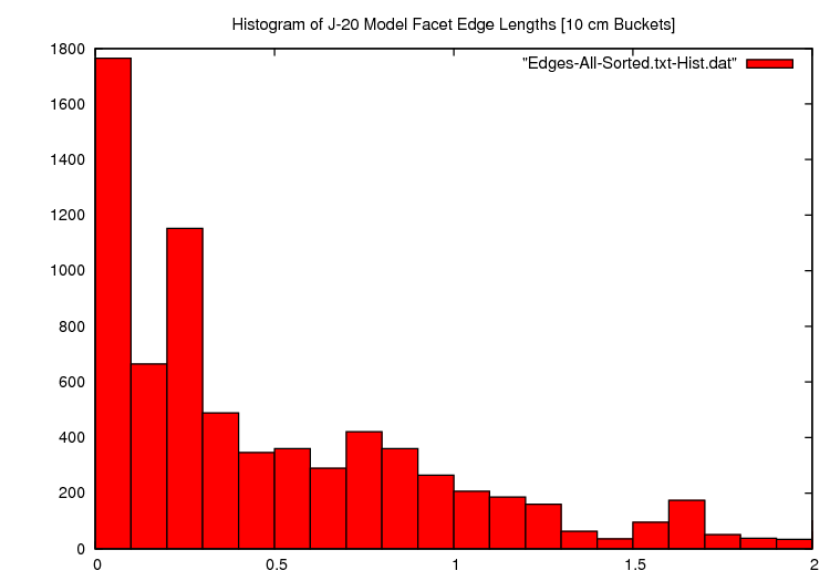
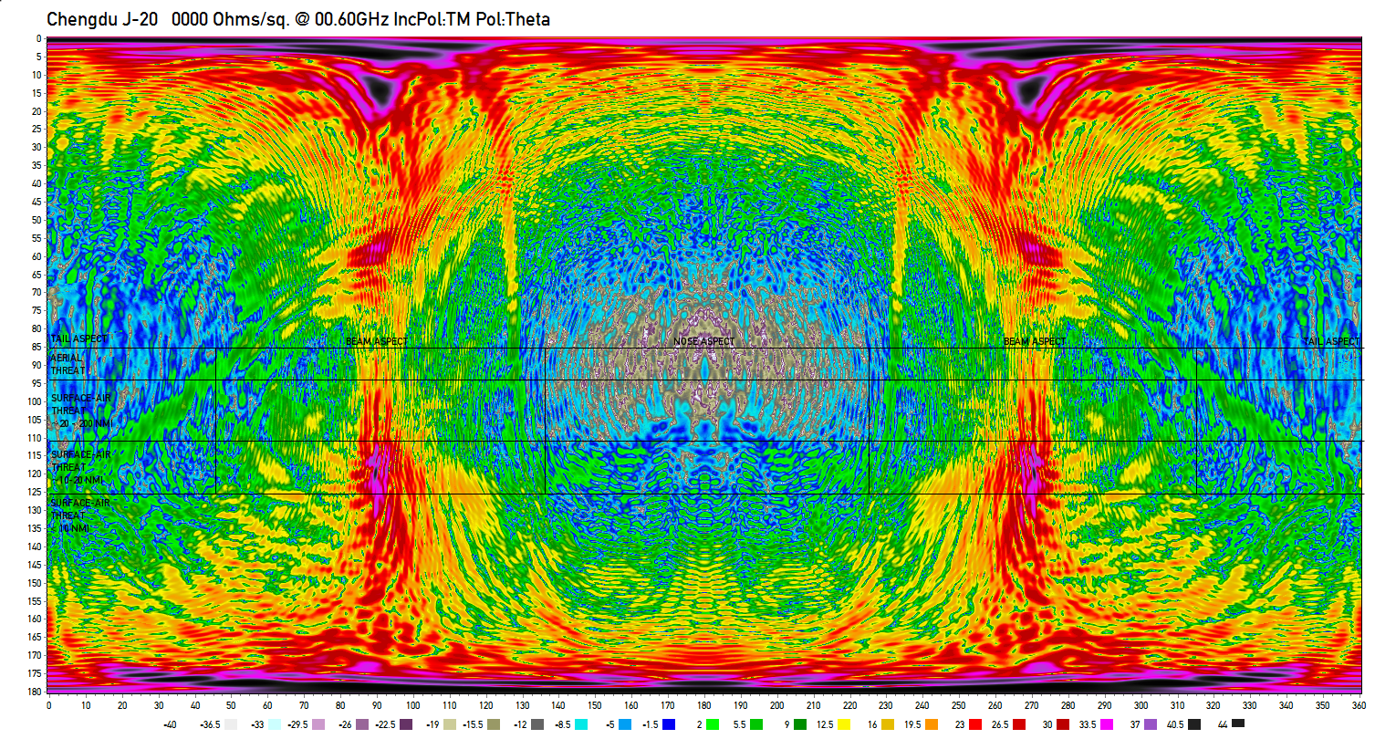
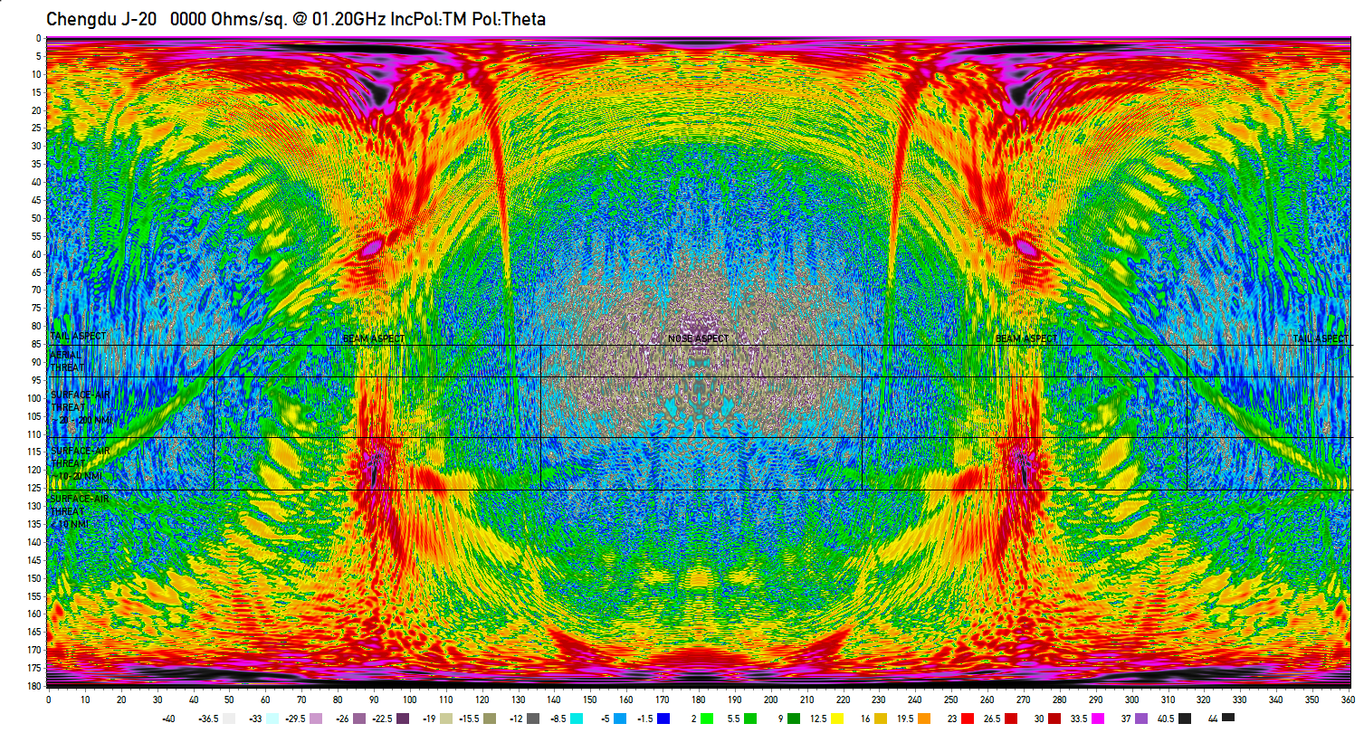
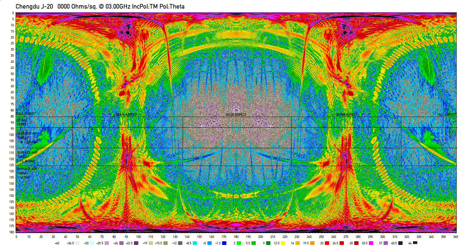
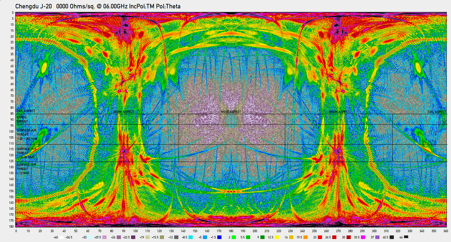
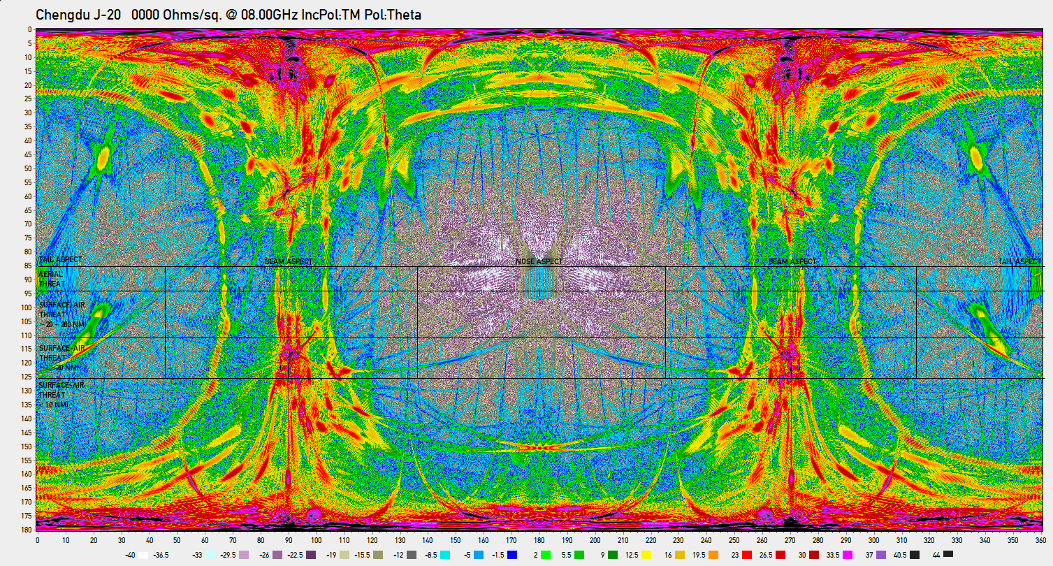
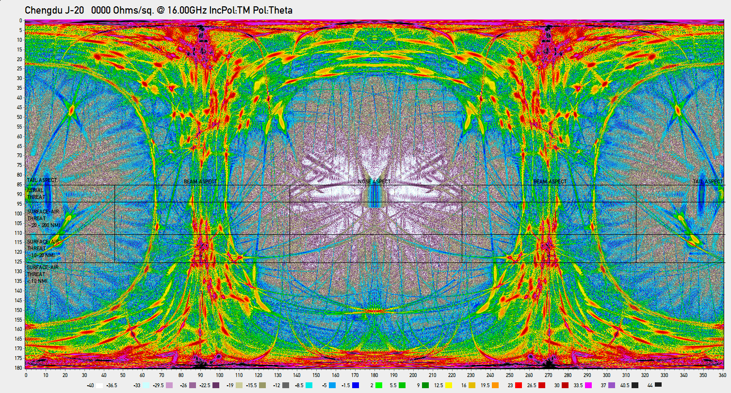
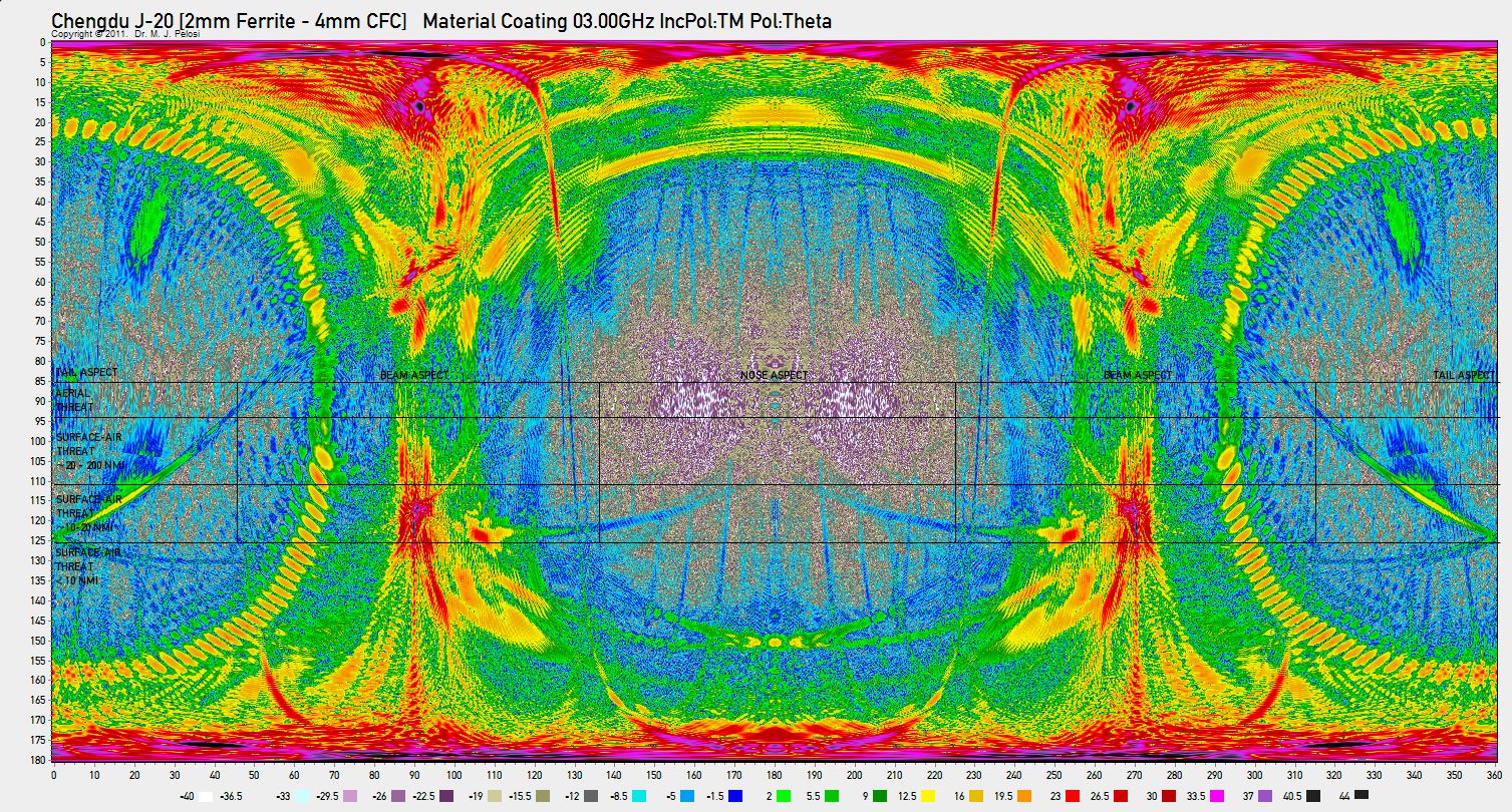
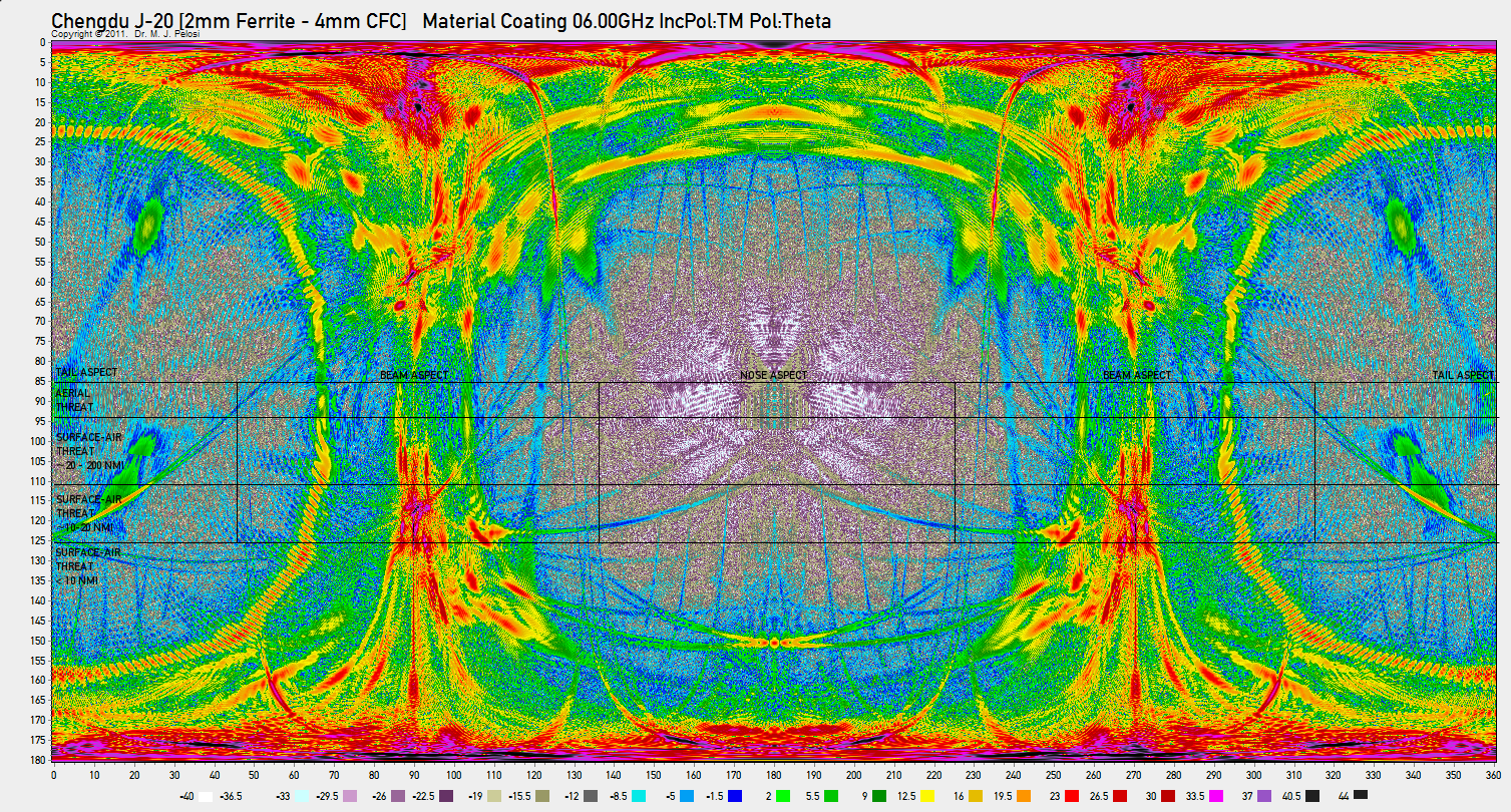
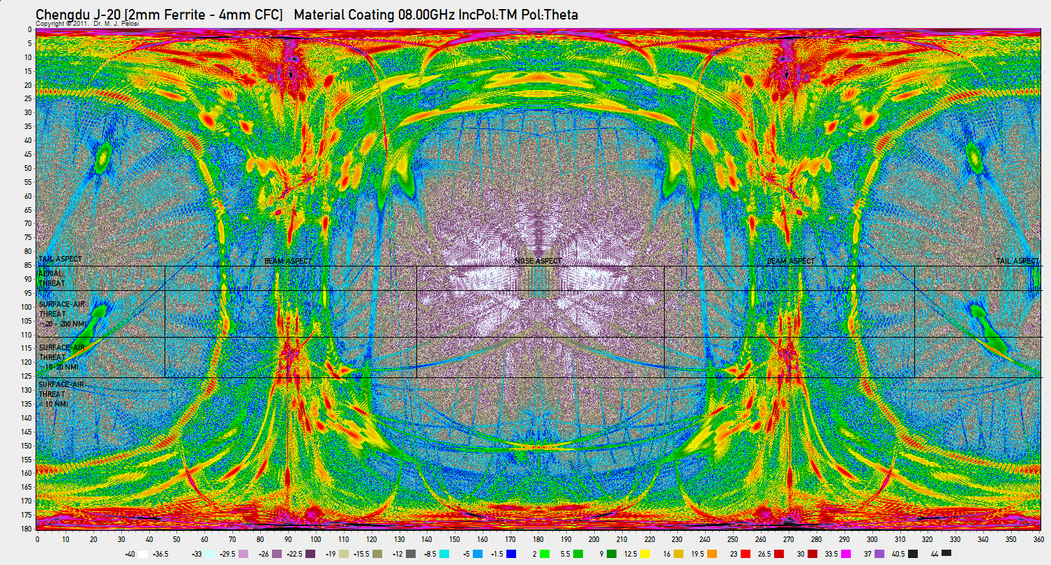
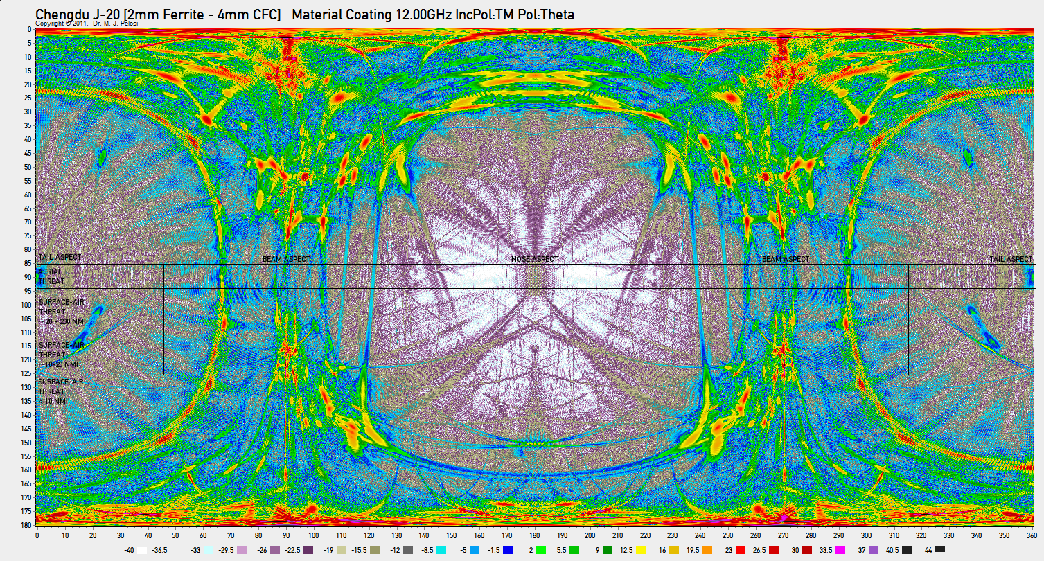
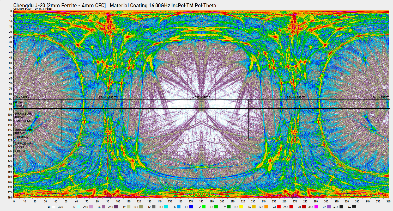
Specular Radar Cross Section Simulation ResultsSpecular RCS was modelled for full spherical all-aspect coverage, for nine frequencies of interest. Frequencies were carefully chosen to match likely threat systems the J-20 would be intended to defeat in an operational environment. There are: 150 MHz to defeat Russian built VHF band Counter-VLO radars such as the Nebo UE, Nebo SVU and Nebo M series, or the Rezonans N/NE series; 600 MHz to defeat UHF band radars such as those carried by the E-2C/D AEW&C system, or the widely used Russian Kasta 2/2E and P-15/19 Flat Face / Squat Eye series; 1.2 GHz to defeat L-band surface based search, acquisition and GCI radars, and the Northrop-Grumman MESA AEW&C radar; 3.0 GHz to defeat widely used S-band acquisition radars, and the E-3 APY-1/APY-2 AWACS system; 6.0 GHz to defeat C-band Surface-Air-Missile engagement radars such as the MPQ-53/65 Patriot system; 8.0 GHz to defeat a range of X-band airborne fighter radars, Surface-Air-Missile engagement radars such as the 30N6E Flap Lid / Tomb Stone, and 92N6E Grave Stone, and a range of Western and Russian Surface-Air-Missile seekers; 12.0 GHz to defeat a range of X-band airborne fighter radars, Surface-Air-Missile engagement radars, and Surface-Air-Missile and Air-Air-Missile seekers; 16.0 GHz to defeat a range of Ku-band airborne fighter radars, and Surface-Air-Missile engagement radars, and Surface-Air-Missile and Air-Air-Missile seekers; 28.0 GHz to defeat a range of K-band missile seekers, and Surface-Air-Missile engagement radars; RCS simulation results are presented in PCSR and PCPR formats. The latter includes rulers to show the most important elevation/depression angle rings/zones, and the four azimuthal quadrants. Analysis of Shape Related Specular Radar Cross SectionThe results of the physical optics simulation modelling of specular RCS for the J-20 shape, using an idealised PEC skin for all external surfaces, are displayed in Tables 1 and 2, for a vertically polarised E component. An additional simulation was performed at 150 MHz, or a horizontally polarised E component, with results in Tables 1A and 2A. Results have been plotted in PCSR format for nine different aspects, and nine different frequencies. PCPR format plots have been produced for nine different frequencies.
The starting point for any forensic analysis of the RCS of a new and hitherto unknown aircraft type is the study of the RCS of its shape, assuming a perfectly electrically conductive surface. This will permit identification of mainlobes and sidelobes, and their respective angular locations. As the simulation technique is confined to the Physical Optics method, care must be taken in the interpretation of results, as at grazing or shallow angles of incidence the method will usually underestimate the magnitude of the RCS. In the most critical nose and tail aspect angular sectors, a good design will have no major scattering sources producing specular returns captured by the simulation, and the RCS will be dominated by nonspecular mechanisms, primarily diffraction and surface travelling waves, engine inlet and exhaust backscatter, as well as the structural mode RCS of antennas, panel join gaps, or other electrical apertures35. Behaviour in the nose aspect angular sector, defined as ±45° in azimuth left and right of the nose, and between +5° in elevation, and -36° in depression, is generally very good across all bands simulated. No scattering sources producing significant specular RCS are observed at 3 GHz or any higher frequencies. The RCS performance will thus satisfy the Very Low Observable requirement that strong specular returns are absent. In this angular and frequency domain, the actual RCS performance of the design will be dominated by edge alignment to control diffracting edge mainlobe directions, and applied RAM and RAS. As the simulation cannot capture the behaviour of the inlet edges and tunnels, these peaks are absent. At L-band and below, there is a pronounced increase in the calculated RCS within the nose aspect angular sector. This is a byproduct of the breakdown of the directional effect produced by smaller shaping features, which lose their ability to concentrate backscatter into narrow mainlobes. Indeed many physically smaller specular and diffractive regime optimised shaping features fall into the Raleigh scattering regime and lose effect wholly. Behaviour in the tail aspect angular sector, defined as ±45° in azimuth left and right of the tail, and between +5° in elevation, and -36° in depression, is dominated by the scattering behaviour of the pair of axisymmetric nozzles, which has major specular, cavity and diffractive contributors, detailed in Annex C. The large diffraction backscatter from the nozzle rims below X-band is not captured in the Physical Optics simulation, the tailpipe cavity backscatter is not represented, and the distinctive lobing structure of the nozzle petals above X-band is also not visible. There are two prominent mainlobes at ~±15° in azimuth left and right of the tail, centred at a depression angle of ~20° to ~40°, produced by the vertical tails which are not shadowed by a horizontal stabilator as would be employed in a conventional airframe design. While these produce strong specular returns, the depression angle through the centre of these mainlobes varies strongly with changing azimuth angle, and thus would present at any fixed depression angle only a narrow transient flash for a single azimuth. Behaviour in the left and right beam aspect angular sectors, defined as ±45° in azimuth left and right of the beam, and between +5° in elevation, and -36° in depression, is dominated by the scattering behaviour of the almost flat slab sides, canted vertical tail surfaces, strakes, and specular return from the nozzles. This could be described as classical “bowtie” lobing behaviour. The specular return from the nozzles produces a pronounced mainlobe at 20° to 25° aft of the airframe beam, through most of the elevation band, with most of the mainlobe contained within a 10° degree width. There is a strong interference pattern discernable in the mainlobe, as the backscatter from the paired nozzles constructively and destructively interferes with changing aspect angle. The primary mainlobe produced by the slab fuselage sides is unusually wide in the azimuthal dimension at ~20° below the S-band as a result of the complex side curvature introduced by area ruling, for aerodynamic reasons. In the Ku-band the mainlobe separates into multiple closely spaced peaks, each associated with a particular extent of the fuselage side. The extent to which the specular mainlobes in a ventral slab sided design, these including the J-20, T-50 PAK-FA, F-35 and F-22, should be made as narrow as possible, depends primarily on whether the aircraft is intended to penetrate an IADS deeply or not. The wider these lobes are, the greater the exposure time of the aircraft to a distant beam aspect threat, such as a missile battery. The overall conclusions which can be drawn from a forensic analysis of the shape of the J-20 prototype across the bands of interest are as follows:
If the production J-20 introduces a rectangular faceted nozzle design, and refinements to fuselage side shaping, the design would present very good potential for robust Very Low Observable performance in the S-band and above, in the nose and tail aspect angular sectors, and viable Low Observable performance above the S-band in the beam aspect angular sector. |
||||||||||||||||||||||||||||||||||||||||||||||||||||||||||||||||||||||||||||||||||||||||||||||||||||||||||||||||||||||||||||||||||||||||||||||||||||||||||||||||||||||||||||||||||||||||||||||||||||||||||||||||||||||||||||||||||||||||||||||||||||||||||||||||||||||||||||||||||||||||||||||||||||||||||||||||||||||||||||||||||||||||||||||||||||||||||||||||||||||||||||||||||||||||||||||||||||||||||||||||||||||||||||||||||||||||||||||||||||||||||||||||||||||||||||||||||||||||||||||||||||||||||||||||||||||||
Analysis of
Specular RCS with a Representative RAM Coating
|
||||||||||||||||||||||||||||||||||||||||||||||||||||||||||||||||||||||||||||||||||||||||||||||||||||||||||||||||||||||||||||||||||||||||||||||||||||||||||||||||||||||||||||||||||||||||||||||||||||||||||||||||||||||||||||||||||||||||||||||||||||||||||||||||||||||||||||||||||||||||||||||||||||||||||||||||||||||||||||||||||||||||||||||||||||||||||||||||||||||||||||||||||||||||||||||||||||||||||||||||||||||||||||||||||||||||||||||||||||||||||||||||||||||||||||||||||||||||||||||||||||||||||||||||||||||||


![Chengdu_J-20_[PEC].mdb-00.15GHz-Rs0000-IncPol-TE-Pol-Phi-[E=000.0_A=000.0]](PLA-VLO/Chengdu_J-20_%5BPEC%5D.mdb-00.15GHz-Rs0000-IncPol-TE-Pol-Phi-%5BE=000.0_A=000.0%5D.png "Chengdu_J-20_[PEC].mdb-00.15GHz-Rs0000-IncPol-TE-Pol-Phi-[E=000.0_A=000.0]")
![Chengdu_J-20_[PEC].mdb-00.15GHz-Rs0000-IncPol-TE-Pol-Phi-[E=180.0_A=180.0]](PLA-VLO/Chengdu_J-20_%5BPEC%5D.mdb-00.15GHz-Rs0000-IncPol-TE-Pol-Phi-%5BE=180.0_A=180.0%5D.png "Chengdu_J-20_[PEC].mdb-00.15GHz-Rs0000-IncPol-TE-Pol-Phi-[E=180.0_A=180.0]")
![Chengdu_J-20_[PEC].mdb-00.15GHz-Rs0000-IncPol-TE-Pol-Phi-[E=090.0_A=180.0]](PLA-VLO/Chengdu_J-20_%5BPEC%5D.mdb-00.15GHz-Rs0000-IncPol-TE-Pol-Phi-%5BE=090.0_A=180.0%5D.png "Chengdu_J-20_[PEC].mdb-00.15GHz-Rs0000-IncPol-TE-Pol-Phi-[E=090.0_A=180.0]")
![Chengdu_J-20_[PEC].mdb-00.15GHz-Rs0000-IncPol-TE-Pol-Phi-[E=090.0_A=000.0]](PLA-VLO/Chengdu_J-20_%5BPEC%5D.mdb-00.15GHz-Rs0000-IncPol-TE-Pol-Phi-%5BE=090.0_A=000.0%5D.png "Chengdu_J-20_[PEC].mdb-00.15GHz-Rs0000-IncPol-TE-Pol-Phi-[E=090.0_A=000.0]")
![Chengdu_J-20_[PEC].mdb-00.15GHz-Rs0000-IncPol-TE-Pol-Phi-[E=090.0_A=270.0]](PLA-VLO/Chengdu_J-20_%5BPEC%5D.mdb-00.15GHz-Rs0000-IncPol-TE-Pol-Phi-%5BE=090.0_A=270.0%5D.png "Chengdu_J-20_[PEC].mdb-00.15GHz-Rs0000-IncPol-TE-Pol-Phi-[E=090.0_A=270.0]")
![Chengdu_J-20_[PEC].mdb-00.15GHz-Rs0000-IncPol-TE-Pol-Phi-[E=045.0_A=225.0]](PLA-VLO/Chengdu_J-20_%5BPEC%5D.mdb-00.15GHz-Rs0000-IncPol-TE-Pol-Phi-%5BE=045.0_A=225.0%5D.png "Chengdu_J-20_[PEC].mdb-00.15GHz-Rs0000-IncPol-TE-Pol-Phi-[E=045.0_A=225.0]")
![Chengdu_J-20_[PEC].mdb-00.15GHz-Rs0000-IncPol-TE-Pol-Phi-[E=135.0_A=225.0]](PLA-VLO/Chengdu_J-20_%5BPEC%5D.mdb-00.15GHz-Rs0000-IncPol-TE-Pol-Phi-%5BE=135.0_A=225.0%5D.png "Chengdu_J-20_[PEC].mdb-00.15GHz-Rs0000-IncPol-TE-Pol-Phi-[E=135.0_A=225.0]")
![Chengdu_J-20_[PEC].mdb-00.15GHz-Rs0000-IncPol-TE-Pol-Phi-[E=045.0_A=315.0]](PLA-VLO/Chengdu_J-20_%5BPEC%5D.mdb-00.15GHz-Rs0000-IncPol-TE-Pol-Phi-%5BE=045.0_A=315.0%5D.png "Chengdu_J-20_[PEC].mdb-00.15GHz-Rs0000-IncPol-TE-Pol-Phi-[E=045.0_A=315.0]")
![Chengdu_J-20_[PEC].mdb-00.15GHz-Rs0000-IncPol-TE-Pol-Phi-[E=135.0_A=315.0]](PLA-VLO/Chengdu_J-20_%5BPEC%5D.mdb-00.15GHz-Rs0000-IncPol-TE-Pol-Phi-%5BE=135.0_A=315.0%5D.png "Chengdu_J-20_[PEC].mdb-00.15GHz-Rs0000-IncPol-TE-Pol-Phi-[E=135.0_A=315.0]")


Table 3.
J-20 Specular RCS Model
Results With RAM / CFC
[V-Pol]
[Click Thumbnail to Enlarge] |
||||||||||
| Frequency |
150 MHz |
600 MHz |
1.2 GHz |
3.0 GHz |
6.0 GHz |
8.0 GHz |
12.0 GHZ |
16.0 GHz |
28.0 GHz |
|
| θ | Φ | Ni-Zn Ferrite / Epoxy RAM / CFC Skin |
||||||||
| 0 | 0 | N/C |
N/C | ![Chengdu-J-20-[2mm-Ferrite---4mm-CFC].mdb-01.20GHz-RsFromCoating-IncPol-TM-Pol-Theta-[E=000.0-A=000.0]](PLA-VLO/Chengdu-J-20-%5B2mm-Ferrite---4mm-CFC%5D.mdb-01.20GHz-RsFromCoating-IncPol-TM-Pol-Theta-%5BE=000.0-A=000.0%5D.png "Chengdu-J-20-[2mm-Ferrite---4mm-CFC].mdb-01.20GHz-RsFromCoating-IncPol-TM-Pol-Theta-[E=000.0-A=000.0]") |
![Chengdu-J-20-[2mm-Ferrite---4mm-CFC].mdb-03.00GHz-RsFromCoating-IncPol-TM-Pol-Theta-[E=000.0-A=000.0]](PLA-VLO/Chengdu-J-20-%5B2mm-Ferrite---4mm-CFC%5D.mdb-03.00GHz-RsFromCoating-IncPol-TM-Pol-Theta-%5BE=000.0-A=000.0%5D.png "Chengdu-J-20-[2mm-Ferrite---4mm-CFC].mdb-03.00GHz-RsFromCoating-IncPol-TM-Pol-Theta-[E=000.0-A=000.0]") |
![Chengdu-J-20-[2mm-Ferrite---4mm-CFC].mdb-06.00GHz-RsFromCoating-IncPol-TM-Pol-Theta-[E=000.0-A=000.0]](PLA-VLO/Chengdu-J-20-%5B2mm-Ferrite---4mm-CFC%5D.mdb-06.00GHz-RsFromCoating-IncPol-TM-Pol-Theta-%5BE=000.0-A=000.0%5D.png "Chengdu-J-20-[2mm-Ferrite---4mm-CFC].mdb-06.00GHz-RsFromCoating-IncPol-TM-Pol-Theta-[E=000.0-A=000.0]") |
![Chengdu-J-20-[2mm-Ferrite---4mm-CFC].mdb-08.00GHz-RsFromCoating-IncPol-TM-Pol-Theta-[E=000.0-A=000.0]](PLA-VLO/Chengdu-J-20-%5B2mm-Ferrite---4mm-CFC%5D.mdb-08.00GHz-RsFromCoating-IncPol-TM-Pol-Theta-%5BE=000.0-A=000.0%5D.png "Chengdu-J-20-[2mm-Ferrite---4mm-CFC].mdb-08.00GHz-RsFromCoating-IncPol-TM-Pol-Theta-[E=000.0-A=000.0]") |
![Chengdu-J-20-[2mm-Ferrite---4mm-CFC].mdb-12.00GHz-RsFromCoating-IncPol-TM-Pol-Theta-[E=000.0-A=000.0]](PLA-VLO/Chengdu-J-20-%5B2mm-Ferrite---4mm-CFC%5D.mdb-12.00GHz-RsFromCoating-IncPol-TM-Pol-Theta-%5BE=000.0-A=000.0%5D.png "Chengdu-J-20-[2mm-Ferrite---4mm-CFC].mdb-12.00GHz-RsFromCoating-IncPol-TM-Pol-Theta-[E=000.0-A=000.0]") |
![Chengdu-J-20-[2mm-Ferrite---4mm-CFC].mdb-16.00GHz-RsFromCoating-IncPol-TM-Pol-Theta-[E=000.0-A=000.0]](PLA-VLO/Chengdu-J-20-%5B2mm-Ferrite---4mm-CFC%5D.mdb-16.00GHz-RsFromCoating-IncPol-TM-Pol-Theta-%5BE=000.0-A=000.0%5D.png "Chengdu-J-20-[2mm-Ferrite---4mm-CFC].mdb-16.00GHz-RsFromCoating-IncPol-TM-Pol-Theta-[E=000.0-A=000.0]") |
N/C |
| 180 | 180 | N/C | N/C | ![Chengdu-J-20-[2mm-Ferrite---4mm-CFC].mdb-01.20GHz-RsFromCoating-IncPol-TM-Pol-Theta-[E=180.0-A=180.0]](PLA-VLO/Chengdu-J-20-%5B2mm-Ferrite---4mm-CFC%5D.mdb-01.20GHz-RsFromCoating-IncPol-TM-Pol-Theta-%5BE=180.0-A=180.0%5D.png "Chengdu-J-20-[2mm-Ferrite---4mm-CFC].mdb-01.20GHz-RsFromCoating-IncPol-TM-Pol-Theta-[E=180.0-A=180.0]") |
![Chengdu-J-20-[2mm-Ferrite---4mm-CFC].mdb-03.00GHz-RsFromCoating-IncPol-TM-Pol-Theta-[E=180.0-A=180.0]](PLA-VLO/Chengdu-J-20-%5B2mm-Ferrite---4mm-CFC%5D.mdb-03.00GHz-RsFromCoating-IncPol-TM-Pol-Theta-%5BE=180.0-A=180.0%5D.png "Chengdu-J-20-[2mm-Ferrite---4mm-CFC].mdb-03.00GHz-RsFromCoating-IncPol-TM-Pol-Theta-[E=180.0-A=180.0]") |
![Chengdu-J-20-[2mm-Ferrite---4mm-CFC].mdb-06.00GHz-RsFromCoating-IncPol-TM-Pol-Theta-[E=180.0-A=180.0]](PLA-VLO/Chengdu-J-20-%5B2mm-Ferrite---4mm-CFC%5D.mdb-06.00GHz-RsFromCoating-IncPol-TM-Pol-Theta-%5BE=180.0-A=180.0%5D.png "Chengdu-J-20-[2mm-Ferrite---4mm-CFC].mdb-06.00GHz-RsFromCoating-IncPol-TM-Pol-Theta-[E=180.0-A=180.0]") |
![Chengdu-J-20-[2mm-Ferrite---4mm-CFC].mdb-08.00GHz-RsFromCoating-IncPol-TM-Pol-Theta-[E=180.0-A=180.0]](PLA-VLO/Chengdu-J-20-%5B2mm-Ferrite---4mm-CFC%5D.mdb-08.00GHz-RsFromCoating-IncPol-TM-Pol-Theta-%5BE=180.0-A=180.0%5D.png "Chengdu-J-20-[2mm-Ferrite---4mm-CFC].mdb-08.00GHz-RsFromCoating-IncPol-TM-Pol-Theta-[E=180.0-A=180.0]") |
![Chengdu-J-20-[2mm-Ferrite---4mm-CFC].mdb-12.00GHz-RsFromCoating-IncPol-TM-Pol-Theta-[E=180.0-A=180.0]](PLA-VLO/Chengdu-J-20-%5B2mm-Ferrite---4mm-CFC%5D.mdb-12.00GHz-RsFromCoating-IncPol-TM-Pol-Theta-%5BE=180.0-A=180.0%5D.png "Chengdu-J-20-[2mm-Ferrite---4mm-CFC].mdb-12.00GHz-RsFromCoating-IncPol-TM-Pol-Theta-[E=180.0-A=180.0]") |
![Chengdu-J-20-[2mm-Ferrite---4mm-CFC].mdb-16.00GHz-RsFromCoating-IncPol-TM-Pol-Theta-[E=180.0-A=180.0]](PLA-VLO/Chengdu-J-20-%5B2mm-Ferrite---4mm-CFC%5D.mdb-16.00GHz-RsFromCoating-IncPol-TM-Pol-Theta-%5BE=180.0-A=180.0%5D.png "Chengdu-J-20-[2mm-Ferrite---4mm-CFC].mdb-16.00GHz-RsFromCoating-IncPol-TM-Pol-Theta-[E=180.0-A=180.0]") |
N/C |
| 090 | 180 | N/C | N/C | ![Chengdu-J-20-[2mm-Ferrite---4mm-CFC].mdb-01.20GHz-RsFromCoating-IncPol-TM-Pol-Theta-[E=090.0-A=180.0]](PLA-VLO/Chengdu-J-20-%5B2mm-Ferrite---4mm-CFC%5D.mdb-01.20GHz-RsFromCoating-IncPol-TM-Pol-Theta-%5BE=090.0-A=180.0%5D.png "Chengdu-J-20-[2mm-Ferrite---4mm-CFC].mdb-01.20GHz-RsFromCoating-IncPol-TM-Pol-Theta-[E=090.0-A=180.0]") |
![Chengdu-J-20-[2mm-Ferrite---4mm-CFC].mdb-03.00GHz-RsFromCoating-IncPol-TM-Pol-Theta-[E=090.0-A=180.0]](PLA-VLO/Chengdu-J-20-%5B2mm-Ferrite---4mm-CFC%5D.mdb-03.00GHz-RsFromCoating-IncPol-TM-Pol-Theta-%5BE=090.0-A=180.0%5D.png "Chengdu-J-20-[2mm-Ferrite---4mm-CFC].mdb-03.00GHz-RsFromCoating-IncPol-TM-Pol-Theta-[E=090.0-A=180.0]") |
![Chengdu-J-20-[2mm-Ferrite---4mm-CFC].mdb-06.00GHz-RsFromCoating-IncPol-TM-Pol-Theta-[E=090.0-A=180.0]](PLA-VLO/Chengdu-J-20-%5B2mm-Ferrite---4mm-CFC%5D.mdb-06.00GHz-RsFromCoating-IncPol-TM-Pol-Theta-%5BE=090.0-A=180.0%5D.png "Chengdu-J-20-[2mm-Ferrite---4mm-CFC].mdb-06.00GHz-RsFromCoating-IncPol-TM-Pol-Theta-[E=090.0-A=180.0]") |
![Chengdu-J-20-[2mm-Ferrite---4mm-CFC].mdb-08.00GHz-RsFromCoating-IncPol-TM-Pol-Theta-[E=090.0-A=180.0]](PLA-VLO/Chengdu-J-20-%5B2mm-Ferrite---4mm-CFC%5D.mdb-08.00GHz-RsFromCoating-IncPol-TM-Pol-Theta-%5BE=090.0-A=180.0%5D.png "Chengdu-J-20-[2mm-Ferrite---4mm-CFC].mdb-08.00GHz-RsFromCoating-IncPol-TM-Pol-Theta-[E=090.0-A=180.0]") |
![Chengdu-J-20-[2mm-Ferrite---4mm-CFC].mdb-12.00GHz-RsFromCoating-IncPol-TM-Pol-Theta-[E=090.0-A=180.0]](PLA-VLO/Chengdu-J-20-%5B2mm-Ferrite---4mm-CFC%5D.mdb-12.00GHz-RsFromCoating-IncPol-TM-Pol-Theta-%5BE=090.0-A=180.0%5D.png "Chengdu-J-20-[2mm-Ferrite---4mm-CFC].mdb-12.00GHz-RsFromCoating-IncPol-TM-Pol-Theta-[E=090.0-A=180.0]") |
![Chengdu-J-20-[2mm-Ferrite---4mm-CFC].mdb-16.00GHz-RsFromCoating-IncPol-TM-Pol-Theta-[E=090.0-A=180.0]](PLA-VLO/Chengdu-J-20-%5B2mm-Ferrite---4mm-CFC%5D.mdb-16.00GHz-RsFromCoating-IncPol-TM-Pol-Theta-%5BE=090.0-A=180.0%5D.png "Chengdu-J-20-[2mm-Ferrite---4mm-CFC].mdb-16.00GHz-RsFromCoating-IncPol-TM-Pol-Theta-[E=090.0-A=180.0]") |
N/C |
| 090 | 0 | N/C | N/C | ![Chengdu-J-20-[2mm-Ferrite---4mm-CFC].mdb-01.20GHz-RsFromCoating-IncPol-TM-Pol-Theta-[E=090.0-A=000.0]](PLA-VLO/Chengdu-J-20-%5B2mm-Ferrite---4mm-CFC%5D.mdb-01.20GHz-RsFromCoating-IncPol-TM-Pol-Theta-%5BE=090.0-A=000.0%5D.png "Chengdu-J-20-[2mm-Ferrite---4mm-CFC].mdb-01.20GHz-RsFromCoating-IncPol-TM-Pol-Theta-[E=090.0-A=000.0]") |
![Chengdu-J-20-[2mm-Ferrite---4mm-CFC].mdb-03.00GHz-RsFromCoating-IncPol-TM-Pol-Theta-[E=090.0-A=000.0]](PLA-VLO/Chengdu-J-20-%5B2mm-Ferrite---4mm-CFC%5D.mdb-03.00GHz-RsFromCoating-IncPol-TM-Pol-Theta-%5BE=090.0-A=000.0%5D.png "Chengdu-J-20-[2mm-Ferrite---4mm-CFC].mdb-03.00GHz-RsFromCoating-IncPol-TM-Pol-Theta-[E=090.0-A=000.0]") |
![Chengdu-J-20-[2mm-Ferrite---4mm-CFC].mdb-06.00GHz-RsFromCoating-IncPol-TM-Pol-Theta-[E=090.0-A=000.0]](PLA-VLO/Chengdu-J-20-%5B2mm-Ferrite---4mm-CFC%5D.mdb-06.00GHz-RsFromCoating-IncPol-TM-Pol-Theta-%5BE=090.0-A=000.0%5D.png "Chengdu-J-20-[2mm-Ferrite---4mm-CFC].mdb-06.00GHz-RsFromCoating-IncPol-TM-Pol-Theta-[E=090.0-A=000.0]") |
![Chengdu-J-20-[2mm-Ferrite---4mm-CFC].mdb-08.00GHz-RsFromCoating-IncPol-TM-Pol-Theta-[E=090.0-A=000.0]](PLA-VLO/Chengdu-J-20-%5B2mm-Ferrite---4mm-CFC%5D.mdb-08.00GHz-RsFromCoating-IncPol-TM-Pol-Theta-%5BE=090.0-A=000.0%5D.png "Chengdu-J-20-[2mm-Ferrite---4mm-CFC].mdb-08.00GHz-RsFromCoating-IncPol-TM-Pol-Theta-[E=090.0-A=000.0]") |
![Chengdu-J-20-[2mm-Ferrite---4mm-CFC].mdb-12.00GHz-RsFromCoating-IncPol-TM-Pol-Theta-[E=090.0-A=000.0]](PLA-VLO/Chengdu-J-20-%5B2mm-Ferrite---4mm-CFC%5D.mdb-12.00GHz-RsFromCoating-IncPol-TM-Pol-Theta-%5BE=090.0-A=000.0%5D.png "Chengdu-J-20-[2mm-Ferrite---4mm-CFC].mdb-12.00GHz-RsFromCoating-IncPol-TM-Pol-Theta-[E=090.0-A=000.0]") |
![Chengdu-J-20-[2mm-Ferrite---4mm-CFC].mdb-16.00GHz-RsFromCoating-IncPol-TM-Pol-Theta-[E=090.0-A=000.0]](PLA-VLO/Chengdu-J-20-%5B2mm-Ferrite---4mm-CFC%5D.mdb-16.00GHz-RsFromCoating-IncPol-TM-Pol-Theta-%5BE=090.0-A=000.0%5D.png "Chengdu-J-20-[2mm-Ferrite---4mm-CFC].mdb-16.00GHz-RsFromCoating-IncPol-TM-Pol-Theta-[E=090.0-A=000.0]") |
N/C |
| 090 | 270 | N/C | N/C | ![Chengdu-J-20-[2mm-Ferrite---4mm-CFC].mdb-01.20GHz-RsFromCoating-IncPol-TM-Pol-Theta-[E=090.0-A=270.0]](PLA-VLO/Chengdu-J-20-%5B2mm-Ferrite---4mm-CFC%5D.mdb-01.20GHz-RsFromCoating-IncPol-TM-Pol-Theta-%5BE=090.0-A=270.0%5D.png "Chengdu-J-20-[2mm-Ferrite---4mm-CFC].mdb-01.20GHz-RsFromCoating-IncPol-TM-Pol-Theta-[E=090.0-A=270.0]") |
![Chengdu-J-20-[2mm-Ferrite---4mm-CFC].mdb-03.00GHz-RsFromCoating-IncPol-TM-Pol-Theta-[E=090.0-A=270.0]](PLA-VLO/Chengdu-J-20-%5B2mm-Ferrite---4mm-CFC%5D.mdb-03.00GHz-RsFromCoating-IncPol-TM-Pol-Theta-%5BE=090.0-A=270.0%5D.png "Chengdu-J-20-[2mm-Ferrite---4mm-CFC].mdb-03.00GHz-RsFromCoating-IncPol-TM-Pol-Theta-[E=090.0-A=270.0]") |
![Chengdu-J-20-[2mm-Ferrite---4mm-CFC].mdb-06.00GHz-RsFromCoating-IncPol-TM-Pol-Theta-[E=090.0-A=270.0]](PLA-VLO/Chengdu-J-20-%5B2mm-Ferrite---4mm-CFC%5D.mdb-06.00GHz-RsFromCoating-IncPol-TM-Pol-Theta-%5BE=090.0-A=270.0%5D.png "Chengdu-J-20-[2mm-Ferrite---4mm-CFC].mdb-06.00GHz-RsFromCoating-IncPol-TM-Pol-Theta-[E=090.0-A=270.0]") |
![Chengdu-J-20-[2mm-Ferrite---4mm-CFC].mdb-08.00GHz-RsFromCoating-IncPol-TM-Pol-Theta-[E=090.0-A=270.0]](PLA-VLO/Chengdu-J-20-%5B2mm-Ferrite---4mm-CFC%5D.mdb-08.00GHz-RsFromCoating-IncPol-TM-Pol-Theta-%5BE=090.0-A=270.0%5D.png "Chengdu-J-20-[2mm-Ferrite---4mm-CFC].mdb-08.00GHz-RsFromCoating-IncPol-TM-Pol-Theta-[E=090.0-A=270.0]") |
![Chengdu-J-20-[2mm-Ferrite---4mm-CFC].mdb-12.00GHz-RsFromCoating-IncPol-TM-Pol-Theta-[E=090.0-A=270.0]](PLA-VLO/Chengdu-J-20-%5B2mm-Ferrite---4mm-CFC%5D.mdb-12.00GHz-RsFromCoating-IncPol-TM-Pol-Theta-%5BE=090.0-A=270.0%5D.png "Chengdu-J-20-[2mm-Ferrite---4mm-CFC].mdb-12.00GHz-RsFromCoating-IncPol-TM-Pol-Theta-[E=090.0-A=270.0]") |
![Chengdu-J-20-[2mm-Ferrite---4mm-CFC].mdb-16.00GHz-RsFromCoating-IncPol-TM-Pol-Theta-[E=090.0-A=270.0]](PLA-VLO/Chengdu-J-20-%5B2mm-Ferrite---4mm-CFC%5D.mdb-16.00GHz-RsFromCoating-IncPol-TM-Pol-Theta-%5BE=090.0-A=270.0%5D.png "Chengdu-J-20-[2mm-Ferrite---4mm-CFC].mdb-16.00GHz-RsFromCoating-IncPol-TM-Pol-Theta-[E=090.0-A=270.0]") |
N/C |
| 045 | 225 | N/C | N/C | ![Chengdu-J-20-[2mm-Ferrite---4mm-CFC].mdb-01.20GHz-RsFromCoating-IncPol-TM-Pol-Theta-[E=045.0-A=225.0]](PLA-VLO/Chengdu-J-20-%5B2mm-Ferrite---4mm-CFC%5D.mdb-01.20GHz-RsFromCoating-IncPol-TM-Pol-Theta-%5BE=045.0-A=225.0%5D.png "Chengdu-J-20-[2mm-Ferrite---4mm-CFC].mdb-01.20GHz-RsFromCoating-IncPol-TM-Pol-Theta-[E=045.0-A=225.0]") |
![Chengdu-J-20-[2mm-Ferrite---4mm-CFC].mdb-03.00GHz-RsFromCoating-IncPol-TM-Pol-Theta-[E=045.0-A=225.0]](PLA-VLO/Chengdu-J-20-%5B2mm-Ferrite---4mm-CFC%5D.mdb-03.00GHz-RsFromCoating-IncPol-TM-Pol-Theta-%5BE=045.0-A=225.0%5D.png "Chengdu-J-20-[2mm-Ferrite---4mm-CFC].mdb-03.00GHz-RsFromCoating-IncPol-TM-Pol-Theta-[E=045.0-A=225.0]") |
![Chengdu-J-20-[2mm-Ferrite---4mm-CFC].mdb-06.00GHz-RsFromCoating-IncPol-TM-Pol-Theta-[E=045.0-A=225.0]](PLA-VLO/Chengdu-J-20-%5B2mm-Ferrite---4mm-CFC%5D.mdb-06.00GHz-RsFromCoating-IncPol-TM-Pol-Theta-%5BE=045.0-A=225.0%5D.png "Chengdu-J-20-[2mm-Ferrite---4mm-CFC].mdb-06.00GHz-RsFromCoating-IncPol-TM-Pol-Theta-[E=045.0-A=225.0]") |
![Chengdu-J-20-[2mm-Ferrite---4mm-CFC].mdb-08.00GHz-RsFromCoating-IncPol-TM-Pol-Theta-[E=045.0-A=225.0]](PLA-VLO/Chengdu-J-20-%5B2mm-Ferrite---4mm-CFC%5D.mdb-08.00GHz-RsFromCoating-IncPol-TM-Pol-Theta-%5BE=045.0-A=225.0%5D.png "Chengdu-J-20-[2mm-Ferrite---4mm-CFC].mdb-08.00GHz-RsFromCoating-IncPol-TM-Pol-Theta-[E=045.0-A=225.0]") |
![Chengdu-J-20-[2mm-Ferrite---4mm-CFC].mdb-12.00GHz-RsFromCoating-IncPol-TM-Pol-Theta-[E=045.0-A=225.0]](PLA-VLO/Chengdu-J-20-%5B2mm-Ferrite---4mm-CFC%5D.mdb-12.00GHz-RsFromCoating-IncPol-TM-Pol-Theta-%5BE=045.0-A=225.0%5D.png "Chengdu-J-20-[2mm-Ferrite---4mm-CFC].mdb-12.00GHz-RsFromCoating-IncPol-TM-Pol-Theta-[E=045.0-A=225.0]") |
![Chengdu-J-20-[2mm-Ferrite---4mm-CFC].mdb-16.00GHz-RsFromCoating-IncPol-TM-Pol-Theta-[E=045.0-A=225.0]](PLA-VLO/Chengdu-J-20-%5B2mm-Ferrite---4mm-CFC%5D.mdb-16.00GHz-RsFromCoating-IncPol-TM-Pol-Theta-%5BE=045.0-A=225.0%5D.png "Chengdu-J-20-[2mm-Ferrite---4mm-CFC].mdb-16.00GHz-RsFromCoating-IncPol-TM-Pol-Theta-[E=045.0-A=225.0]") |
N/C |
| 135 | 225 | N/C | N/C | ![Chengdu-J-20-[2mm-Ferrite---4mm-CFC].mdb-01.20GHz-RsFromCoating-IncPol-TM-Pol-Theta-[E=135.0-A=225.0]](PLA-VLO/Chengdu-J-20-%5B2mm-Ferrite---4mm-CFC%5D.mdb-01.20GHz-RsFromCoating-IncPol-TM-Pol-Theta-%5BE=135.0-A=225.0%5D.png "Chengdu-J-20-[2mm-Ferrite---4mm-CFC].mdb-01.20GHz-RsFromCoating-IncPol-TM-Pol-Theta-[E=135.0-A=225.0]") |
![Chengdu-J-20-[2mm-Ferrite---4mm-CFC].mdb-03.00GHz-RsFromCoating-IncPol-TM-Pol-Theta-[E=135.0-A=225.0]](PLA-VLO/Chengdu-J-20-%5B2mm-Ferrite---4mm-CFC%5D.mdb-03.00GHz-RsFromCoating-IncPol-TM-Pol-Theta-%5BE=135.0-A=225.0%5D.png "Chengdu-J-20-[2mm-Ferrite---4mm-CFC].mdb-03.00GHz-RsFromCoating-IncPol-TM-Pol-Theta-[E=135.0-A=225.0]") |
![Chengdu-J-20-[2mm-Ferrite---4mm-CFC].mdb-06.00GHz-RsFromCoating-IncPol-TM-Pol-Theta-[E=135.0-A=225.0]](PLA-VLO/Chengdu-J-20-%5B2mm-Ferrite---4mm-CFC%5D.mdb-06.00GHz-RsFromCoating-IncPol-TM-Pol-Theta-%5BE=135.0-A=225.0%5D.png "Chengdu-J-20-[2mm-Ferrite---4mm-CFC].mdb-06.00GHz-RsFromCoating-IncPol-TM-Pol-Theta-[E=135.0-A=225.0]") |
![Chengdu-J-20-[2mm-Ferrite---4mm-CFC].mdb-08.00GHz-RsFromCoating-IncPol-TM-Pol-Theta-[E=135.0-A=225.0]](PLA-VLO/Chengdu-J-20-%5B2mm-Ferrite---4mm-CFC%5D.mdb-08.00GHz-RsFromCoating-IncPol-TM-Pol-Theta-%5BE=135.0-A=225.0%5D.png "Chengdu-J-20-[2mm-Ferrite---4mm-CFC].mdb-08.00GHz-RsFromCoating-IncPol-TM-Pol-Theta-[E=135.0-A=225.0]") |
![Chengdu-J-20-[2mm-Ferrite---4mm-CFC].mdb-12.00GHz-RsFromCoating-IncPol-TM-Pol-Theta-[E=135.0-A=225.0]](PLA-VLO/Chengdu-J-20-%5B2mm-Ferrite---4mm-CFC%5D.mdb-12.00GHz-RsFromCoating-IncPol-TM-Pol-Theta-%5BE=135.0-A=225.0%5D.png "Chengdu-J-20-[2mm-Ferrite---4mm-CFC].mdb-12.00GHz-RsFromCoating-IncPol-TM-Pol-Theta-[E=135.0-A=225.0]") |
![Chengdu-J-20-[2mm-Ferrite---4mm-CFC].mdb-16.00GHz-RsFromCoating-IncPol-TM-Pol-Theta-[E=135.0-A=225.0]](PLA-VLO/Chengdu-J-20-%5B2mm-Ferrite---4mm-CFC%5D.mdb-16.00GHz-RsFromCoating-IncPol-TM-Pol-Theta-%5BE=135.0-A=225.0%5D.png "Chengdu-J-20-[2mm-Ferrite---4mm-CFC].mdb-16.00GHz-RsFromCoating-IncPol-TM-Pol-Theta-[E=135.0-A=225.0]") |
N/C |
| 045 | 315 | N/C | N/C | ![Chengdu-J-20-[2mm-Ferrite---4mm-CFC].mdb-01.20GHz-RsFromCoating-IncPol-TM-Pol-Theta-[E=045.0-A=315.0]](PLA-VLO/Chengdu-J-20-%5B2mm-Ferrite---4mm-CFC%5D.mdb-01.20GHz-RsFromCoating-IncPol-TM-Pol-Theta-%5BE=045.0-A=315.0%5D.png "Chengdu-J-20-[2mm-Ferrite---4mm-CFC].mdb-01.20GHz-RsFromCoating-IncPol-TM-Pol-Theta-[E=045.0-A=315.0]") |
![Chengdu-J-20-[2mm-Ferrite---4mm-CFC].mdb-03.00GHz-RsFromCoating-IncPol-TM-Pol-Theta-[E=045.0-A=315.0]](PLA-VLO/Chengdu-J-20-%5B2mm-Ferrite---4mm-CFC%5D.mdb-03.00GHz-RsFromCoating-IncPol-TM-Pol-Theta-%5BE=045.0-A=315.0%5D.png "Chengdu-J-20-[2mm-Ferrite---4mm-CFC].mdb-03.00GHz-RsFromCoating-IncPol-TM-Pol-Theta-[E=045.0-A=315.0]") |
![Chengdu-J-20-[2mm-Ferrite---4mm-CFC].mdb-06.00GHz-RsFromCoating-IncPol-TM-Pol-Theta-[E=045.0-A=315.0]](PLA-VLO/Chengdu-J-20-%5B2mm-Ferrite---4mm-CFC%5D.mdb-06.00GHz-RsFromCoating-IncPol-TM-Pol-Theta-%5BE=045.0-A=315.0%5D.png "Chengdu-J-20-[2mm-Ferrite---4mm-CFC].mdb-06.00GHz-RsFromCoating-IncPol-TM-Pol-Theta-[E=045.0-A=315.0]") |
![Chengdu-J-20-[2mm-Ferrite---4mm-CFC].mdb-08.00GHz-RsFromCoating-IncPol-TM-Pol-Theta-[E=045.0-A=315.0]](PLA-VLO/Chengdu-J-20-%5B2mm-Ferrite---4mm-CFC%5D.mdb-08.00GHz-RsFromCoating-IncPol-TM-Pol-Theta-%5BE=045.0-A=315.0%5D.png "Chengdu-J-20-[2mm-Ferrite---4mm-CFC].mdb-08.00GHz-RsFromCoating-IncPol-TM-Pol-Theta-[E=045.0-A=315.0]") |
![Chengdu-J-20-[2mm-Ferrite---4mm-CFC].mdb-12.00GHz-RsFromCoating-IncPol-TM-Pol-Theta-[E=045.0-A=315.0]](PLA-VLO/Chengdu-J-20-%5B2mm-Ferrite---4mm-CFC%5D.mdb-12.00GHz-RsFromCoating-IncPol-TM-Pol-Theta-%5BE=045.0-A=315.0%5D.png "Chengdu-J-20-[2mm-Ferrite---4mm-CFC].mdb-12.00GHz-RsFromCoating-IncPol-TM-Pol-Theta-[E=045.0-A=315.0]") |
![Chengdu-J-20-[2mm-Ferrite---4mm-CFC].mdb-16.00GHz-RsFromCoating-IncPol-TM-Pol-Theta-[E=045.0-A=315.0]](PLA-VLO/Chengdu-J-20-%5B2mm-Ferrite---4mm-CFC%5D.mdb-16.00GHz-RsFromCoating-IncPol-TM-Pol-Theta-%5BE=045.0-A=315.0%5D.png "Chengdu-J-20-[2mm-Ferrite---4mm-CFC].mdb-16.00GHz-RsFromCoating-IncPol-TM-Pol-Theta-[E=045.0-A=315.0]") |
N/C |
| 135 | 315 | N/C | N/C | ![Chengdu-J-20-[2mm-Ferrite---4mm-CFC].mdb-01.20GHz-RsFromCoating-IncPol-TM-Pol-Theta-[E=135.0-A=315.0]](PLA-VLO/Chengdu-J-20-%5B2mm-Ferrite---4mm-CFC%5D.mdb-01.20GHz-RsFromCoating-IncPol-TM-Pol-Theta-%5BE=135.0-A=315.0%5D.png "Chengdu-J-20-[2mm-Ferrite---4mm-CFC].mdb-01.20GHz-RsFromCoating-IncPol-TM-Pol-Theta-[E=135.0-A=315.0]") |
![Chengdu-J-20-[2mm-Ferrite---4mm-CFC].mdb-03.00GHz-RsFromCoating-IncPol-TM-Pol-Theta-[E=135.0-A=315.0]](PLA-VLO/Chengdu-J-20-%5B2mm-Ferrite---4mm-CFC%5D.mdb-03.00GHz-RsFromCoating-IncPol-TM-Pol-Theta-%5BE=135.0-A=315.0%5D.png "Chengdu-J-20-[2mm-Ferrite---4mm-CFC].mdb-03.00GHz-RsFromCoating-IncPol-TM-Pol-Theta-[E=135.0-A=315.0]") |
![Chengdu-J-20-[2mm-Ferrite---4mm-CFC].mdb-06.00GHz-RsFromCoating-IncPol-TM-Pol-Theta-[E=135.0-A=315.0]](PLA-VLO/Chengdu-J-20-%5B2mm-Ferrite---4mm-CFC%5D.mdb-06.00GHz-RsFromCoating-IncPol-TM-Pol-Theta-%5BE=135.0-A=315.0%5D.png "Chengdu-J-20-[2mm-Ferrite---4mm-CFC].mdb-06.00GHz-RsFromCoating-IncPol-TM-Pol-Theta-[E=135.0-A=315.0]") |
![Chengdu-J-20-[2mm-Ferrite---4mm-CFC].mdb-08.00GHz-RsFromCoating-IncPol-TM-Pol-Theta-[E=135.0-A=315.0]](PLA-VLO/Chengdu-J-20-%5B2mm-Ferrite---4mm-CFC%5D.mdb-08.00GHz-RsFromCoating-IncPol-TM-Pol-Theta-%5BE=135.0-A=315.0%5D.png "Chengdu-J-20-[2mm-Ferrite---4mm-CFC].mdb-08.00GHz-RsFromCoating-IncPol-TM-Pol-Theta-[E=135.0-A=315.0]") |
![Chengdu-J-20-[2mm-Ferrite---4mm-CFC].mdb-12.00GHz-RsFromCoating-IncPol-TM-Pol-Theta-[E=135.0-A=315.0]](PLA-VLO/Chengdu-J-20-%5B2mm-Ferrite---4mm-CFC%5D.mdb-12.00GHz-RsFromCoating-IncPol-TM-Pol-Theta-%5BE=135.0-A=315.0%5D.png "Chengdu-J-20-[2mm-Ferrite---4mm-CFC].mdb-12.00GHz-RsFromCoating-IncPol-TM-Pol-Theta-[E=135.0-A=315.0]") |
![Chengdu-J-20-[2mm-Ferrite---4mm-CFC].mdb-16.00GHz-RsFromCoating-IncPol-TM-Pol-Theta-[E=135.0-A=315.0]](PLA-VLO/Chengdu-J-20-%5B2mm-Ferrite---4mm-CFC%5D.mdb-16.00GHz-RsFromCoating-IncPol-TM-Pol-Theta-%5BE=135.0-A=315.0%5D.png "Chengdu-J-20-[2mm-Ferrite---4mm-CFC].mdb-16.00GHz-RsFromCoating-IncPol-TM-Pol-Theta-[E=135.0-A=315.0]") |
N/C |
dBSM Scale |
||||||||||
 |
||||||||||
|
Table 4. J-20 Specular RCS Model Results With RAM / CFC [V-Pol] [Click Chart to Enlarge] |
|||||||||||||||||||||||||||
| 1.2 GHz | |||||||||||||||||||||||||||
![Chengdu_J-20_[2mm_Ferrite_-_4mm_CFC].mdb-01.20GHz-RsFromCoating-IncPol-TM-Pol-Theta](PLA-VLO/Chengdu_J-20_%5B2mm_Ferrite_-_4mm_CFC%5D.mdb-01.20GHz-RsFromCoating-IncPol-TM-Pol-Theta.png "Chengdu_J-20_[2mm_Ferrite_-_4mm_CFC].mdb-01.20GHz-RsFromCoating-IncPol-TM-Pol-Theta") |
|||||||||||||||||||||||||||
| 3.0 GHz | |||||||||||||||||||||||||||
 |
|||||||||||||||||||||||||||
| 6.0 GHz | |||||||||||||||||||||||||||
 |
|||||||||||||||||||||||||||
| 8.0 GHz | |||||||||||||||||||||||||||
 |
|||||||||||||||||||||||||||
| 12.0 GHZ | |||||||||||||||||||||||||||
 |
|||||||||||||||||||||||||||
| 16.0 GHz | |||||||||||||||||||||||||||
 |
|||||||||||||||||||||||||||
|
|||||||||||||||||||||||||||
| Table 5.
Representative RAM
and Material Properties |
|||||||
| Material |
Thickness d [mm] |
Frequency f [GHz] |
Resistivity ρ [Ω·m] |
Permittivity εr [-] |
Permeability μr [-] |
||
| Real εr |
Loss Tangent δ |
Real μr' |
Imaginary μr" |
||||
| A CNT/Epoxy1 | 1.0 |
||||||
| 0.1502 |
14.0 |
0.42 |
1.02 |
0.08 |
|||
| 0.6002 |
14.0 | 0.42 | 1.02 | 0.08 | |||
| 1.2 |
14.0 | 0.42 | 1.02 | 0.08 | |||
| 2.0 |
14.0 |
0.42 | 1.02 |
0.08 |
|||
| 3.0 |
14.0 | 0.42 | 1.02 | 0.08 | |||
| 6.0 |
14.0 | 0.43 |
1.05 |
0.09 |
|||
| 8.0 |
14.0 | 0.435 |
1.08 |
0.10 |
|||
| 12.0 |
14.0 | 0.443 |
1.11 |
0.105 |
|||
| 16.0 | 14.0 | 0.45 |
1.14 |
0.11 |
|||
| 28.0 |
14.0 | 0.58 |
1.1 |
0.01 |
|||
| B Ferrite/Epoxy3 | 2.0-3.0 |
||||||
| 1.24 | 4.7 |
0.064 | 1.15 |
1.2 |
|||
| 3.04 | 4.7 |
0.064 | 1.1 |
0.80 |
|||
| 6.0 | 4.6 |
0.065 | 0.90 |
0.38 |
|||
| 8.0 | 4.9 |
0.061 | 0.8 |
0.20 |
|||
| 12.0 | 5.0 |
0.060 | 0.95 |
0.08 |
|||
| 16.04 | 5.0 |
0.060 | 0.95 | 0.08 | |||
| C Ferrite/Epoxy/CFC3 | 6.0
(CFC) |
||||||
| 1.24 | 25.0 | 0.12 | 1.15 |
1.2 |
|||
| 3.04 | 25.0 |
0.12 |
1.1 |
0.80 |
|||
| 6.0 | 22.0 |
0.18 | 0.90 |
0.38 |
|||
| 8.0 | 23.0 |
0.30 |
0.8 |
0.20 |
|||
| 12.0 | 15.0 |
0.53 |
0.95 |
0.08 |
|||
| 16.04 | 7.50 |
1.46 |
0.95 | 0.08 | |||
| Carbon Fibre
Composite5 |
- |
||||||
| 4.0 | 25.0 |
0.12 |
1.0 |
0.0 | |||
| 6.0 | 20.0 |
0.18 |
1.0 |
0.0 | |||
| 8.0 | 20.0 |
0.25 |
1.0 |
0.0 | |||
| 12.0 | 15.0 |
0.50 |
1.1 |
0.0 | |||
| Silver/Epoxy |
0.2 |
0.15
-
28.0 |
~1.59×10⁻⁸ | N/A | N/A | 0.99998 | 0.0 |
| Aluminium |
3.0 |
0.15 - 28.0 | 2.82×10⁻⁸ | N/A | N/A | 1.000022 | 0.0 |
| Epoxy
Matrix |
0.2 |
0.15 - 28.0 | Very High |
4.6
- 3.0 |
0.01 | 1.0 | 0.0 |
| Notes: | |||||||
| 1
-
Zhang et al, 2009. 2 - Extrapolated from Zhang et al. 3 - Kim et al, 1997, KST, 2(b) Ni-Zn ferrite filler, ~3 mm loaded epoxy and ~3 mm CFC skin. 4 - Extrapolated from Kim et al, 1997, 2(b), using Ni-Zn ferrite frequency dependency properties for εr and μr. 5 - Kim et al, 2007. |
|||||||
Conclusions
This study has explored the specular Radar Cross Section of the Chengdu J-20 prototype aircraft shaping design. Simulations using a Physical Optics simulation algorithm were performed for frequencies of 150 MHz, 600 MHz, 1.2 GHz, 3.0 GHz, 6.0 GHz, 8.0 GHz, 12.0 GHz, 16.0 GHz and 28 GHz without an absorbent coating, and for frequencies of 1.2 GHz, 3.0 GHz, 6.0 GHz, 8.0 GHz, 12.0 GHz, 16.0 GHz with an absorbent coating, covering all angular aspects of the airframe.
In addition, the performance of a range of Chinese developed radar absorbers was modelled, based on a reasonable survey of unclassified Chinese research publications in the area. None of the surveyed materials were found to be suitable for use as impedance matched specular radar absorbers.
If the production J-20 retains the axisymmetric nozzles and smoothly area ruled sides, the aircraft could at best deliver robust Very Low Observable performance in the nose aspect angular sector.
If the production J-20 introduces a rectangular faceted nozzle design, and refinements to fuselage side shaping, the design would present very good potential for robust Very Low Observable performance in the S-band and above, for the nose and tail aspect angular sectors, with good performance in the beam aspect angular sector.
In conclusion, this study has established through Physical Optics simulation across nine frequency bands, that no fundamental obstacles exist in the shaping design of the J-20 prototype, which would preclude its development into a genuine Very Low Observable design.
Endnotes, References and Bibliography:
1 Knott, E.F., Schaeffer, J.F. and Tuley, M.T., Radar Cross Section, First Edition, Artech House, 1986; Knott, E.F., Schaeffer, J.F. and Tuley, M.T., Radar Cross Section, Second Edition, Artech House, 1993.
2 Kopp, C. and Goon, P.A., Assessing the Sukhoi PAK-FA; Sukhoi/KnAAPO T-50/I-21/Article 701 PAK-FA; Перспективный Авиационный Комплекс Фронтовой Авиации, APA Analyses APA-2010-1, Vol. VII APA-2010-01, Feb 2010, URI: http://www.ausairpower.net/APA-2010-01.html.
3 Kopp, C., Assessing Joint Strike Fighter Defence Penetration Capabilities, Air Power Australia Analysis 2009-01, 7th January 2009, URI: http://www.ausairpower.net/APA-2009-01.html
4 Kopp, C. and Goon, P.A., Chengdu J-20 Stealth Fighter Prototype; A Preliminary Assessment, Technical Report APA-TR-2011-0101, January 2011, URI: http://www.ausairpower.net/APA-J-XX-Prototype.html.
5 Chatzigeorgiadis, F., DEVELOPMENT OF CODE FOR A PHYSICAL OPTICS RADAR CROSS SECTION PREDICTION AND ANALYSIS APPLICATION, M.S. Thesis, NAVAL POSTGRADUATE SCHOOL, MONTEREY, CALIFORNIA, September 2004; Garrido, E.E. Jr, GRAPHICAL USER INTERFACE FOR A PHYSICAL OPTICS RADAR CROSS SECTION PREDICTION CODE, M.S. Thesis, NAVAL POSTGRADUATE SCHOOL, MONTEREY, CALIFORNIA, September 2000; Chatzigeorgiadis, F. and Jenn, D.C., “A MATLAB Physical Optics Prediction Code,” IEEE Antennas and Propagation Magazine, Vol. 46, No. 4, pp. 137-139, August 2004.
6 Gao, Z.H. and Wang, M.L., An Efficient Algorithm for Calculating Aircraft RCS Based on the Geometrical Characteristics, Chinese Journal of Aeronautics, Volume 21, Issue 4, August 2008, Pages 296-303.
7 Jiang, L.Y. et al., Design of high performance multilayer microwave absorbers using fast Pareto genetic algorithm,
Science in China Series E:
Technological Sciences, Volume 52, Number 9, 2749-2757, DOI:
10.1007/s11431-009-0145-x, Springer Verlag, 2009.
8 Cao, M.S. et al., Computation design and performance prediction towards a multi-layer microwave absorber, Materials & Design, Volume 23, Issue 6, September 2002, Pages 557-564.
8 Cao, M.S. et al., Computation design and performance prediction towards a multi-layer microwave absorber, Materials & Design, Volume 23, Issue 6, September 2002, Pages 557-564.
10 Che, R.C. et al., Microwave Absorption Enhancement and Complex Permittivity and Permeability of Fe Encapsulated within Carbon Nanotubes. Advanced Materials, 16: 401–405. doi: 10.1002/adma.200306460, 2004.
11 Du J.H et al, The present status and key problems of carbon nanotube based polymer composites, eXPRESS Polymer Letters Vol.1, No.5 (2007) 253–273.
12 Gan, Y.X., Permeability and permittivity measurement and reflectivity calculation for a microwave-absorbing composite material containing a resonator and an electromagnetic loss substance, Composites, Volume 23, Issue 6, November 1992, Pages 435-439.
13 Gui, X.C. et al., Optimization of electromagnetic matching of Fe-filled carbon nanotubes/ferrite composites for microwave absorption, J. Phys. D: Appl. Phys. 42 (2009), 075002, IOP Publishing Ltd, 2009.
14 Gui, X.C. et al., Microwave absorbing properties and magnetic properties of different carbon nanotubes, Science in China Series E: Technological Sciences, Volume 52, Number 1, 227-231, DOI: 10.1007/s11431-009-0020-9, June 2009, Springer Verlag.
15 Han, M.G. et al., Microwave Absorbing Properties of Amorphous FeCuNbSiB Microwires Multilayer Composites, ELECTROMAGNETIC MATERIALS, Proceedings of the Symposium P (ICMAT 2007), SUNTEC, Singapore, 1 - 6 July 2007.
16 Li, Q.H. et al., Study on the Microwave Permeability of the CNT Complex in 2-18 GHz, Applied Physics Research Vol. 2, No. 2; Canadian Center of Science and Education, November 2010.
17 Li, B.W. et al., Enhanced microwave absorption in nickel/hexagonal-ferrite/polymer composites, Appl. Phys. Lett. 89, 132504 (2006); doi:10.1063/1.2357565, September, 2006.
18 Liu, Z. et al., Microwave Absorption of Single-Walled Carbon Nanotubes/Soluble Cross-Linked Polyurethane Composites, J. Phys. Chem., 111, 13696-13700, American Chemical Society.
19 Qing, Y.C. et al., Electromagnetic and Absorbing Properties of Multi-walled Carbon Nanotubes/Epoxy-silicone Coatings, Journal of Inorganic Materials, 2010-02, (Abstract).
20 Zhang, X.F., High permittivity from defective carbon-coated Cu nanocapsules, Nanotechnology 18 275701, doi: 10.1088/0957-4484/18/27/275701, 2007.
21 Zhang, X. et al., Microwave Permittivity and Permeability of Activated Carbon Fibers Imbedded in Paraffin Wax, Conference Proceedings, American Carbon Society, Lexington, KY, July 14-19, 2001.
22 Zhang, Z. et al., Absorption properties of radar absorbing structure laminate composites filled with carbon nanotubes, Carbon – Sci. Tech. 3 (2009) 117 - 119, Applied Science Innovations Pvt. Ltd., India.
23 Zhao, D.L., COMPLEX PERMITTIVITY AND PERMEABILITY OF NI-COATED CARBON NANOTUBE / POLYMER COMPOSITES, Proceedings of the 35th ISTC, Dayton, Ohio, September 28, Society for the Advancement of Material and Process Engineering, October 2, 2003.
24 Zhao, D.L., et al., Formation Mechanism and Microwave Permittivity of Carbon Nanotubes Filled with Metallic Silver Nanowires, Key Engineering Materials, 334-335, 685, 2007.
25 Zhao, D.L., COMPLEX PERMITTIVITY AND PERMEABILITY OF CARBON NANOTUBES AT 26-40GHZ, Conference Proceedings, American Carbon Society, Brown University, Providence, RI, July 11-16, 2004.
26 Zhao, D.L. et al., Preparation of Carbon Nanotube Reinforced Epoxy Resin Coating and its Microwave Characteristics, Key Engineering Materials, Vol. 334-335, 677, March, 2007.
27 Zhao, D.L. et al., Microwave Permittivity and Permeability of Ni-Coated Carbon Nanotube / Polymer Composites, Key Engineering Materials, 334-335, 681, March, 2007.
28 Zhao, D.L. et al., Formation Mechanism and Microwave Permittivity of Carbon Nanotubes Filled with Metallic Silver Nanowires, Key Engineering Materials, 334-335, 685, March, 2007.
29 Yan, L.G. et al., Broadband and thin microwave absorber of nickel–zinc ferrite/carbonyl iron composite, Journal of Alloys and Compounds, Volume 487, Issues 1-2, 13 November 2009, Pages 708-711, Elsevier B.V., 2009.
30 Yuping, D. et al., The microwave electromagnetic characteristics of manganese dioxide with different crystallographic structures, Physica B: Condensed Matter, Volume 405, Issue 7, 1 April 2010, Pages 1826-1831, Elsevier B.V.
31 Wang, M. et al., Absorption properties of carbonyl-iron/carbon black double-layer microwave absorbers , Journal of Magnetism and Magnetic Materials, Volume 321, Issue 20, October 2009, Pages 3442-3446, Elsevier B.V.
32 Kim, S.S., Cheong, G.M. and Yoon, B.I., Ferrite-Epoxy Absorber on Carbon Fiber Composite Substrate, J. PHYS IV FRANCE 7 ( 1997), Colloque C1, Supplement au Journal de Physique 111 de mars 1997, EDP Sciences; also Kim S.H. et al, Double-layered microwave absorbers composed of ferrite and carbon fiber composite laminates, phys. stat. sol. (c) 4, No. 12, 4602–4605 (2007) / DOI 10.1002/pssc.200777374, WILEY-VCH Verlag GmbH & Co. KGaA, Weinheim.
33 Saville, P., A review of optimisation techniques for layered radar absorbing materials, Technical memorandum 2005-003, Defence R&D Canada; and Saville, P.. 2005. Review of Radar Absorbing Materials. DRDC Atlantic TM 2005-003, DRDC Atlantic.
34 Tuley, M.T. in Ch.8 (1).
35 Yuzcelik, C.K, Radar Absorbing Material Design, M.S.Thesis, Naval Postgraduate School, Monterey, California, September, 2003.
36 Schaeffer, J.F. in Ch.14 (1).
37 Kim, S.H. et al., Double-layered microwave absorbers composed of ferrite and carbon fiber composite laminates, phys. stat. sol. (c) 4, No. 12, 4602–4605 (2007) / DOI 10.1002/pssc.200777374, WILEY-VCH Verlag GmbH & Co. KGaA, Weinheim, December, 2007.
38 Barton, D.K. and Leonov, S.A., Editors, Radar Technology Encyclopedia, Artech House, Massachussetts, 1998, 0-89006-893-3.
39 Mitzner, K.M., Incremental Length Diffraction Coefficients, Technical Report AFAL-TR-73-296, Air Force Avionic Laboratory, Air Force Systems Command, WPAFB, April, 1974.
40 Stroobandt, S., The Characterization of Surface Waves on Low-Observable Structures, MSc Thesis, University of Hull, August, 1997.
Annex A Scales,
Bands,
Geometries,
and
Representative
Threats
| dBSM |
30 |
20 |
10 |
0 |
-10 |
-20 |
-30 |
-40 |
-50 |
|||||
| m2 |
1,000.0 |
100.0 |
10.0 |
1.0 |
0.1 |
0.01 |
0.001 |
0.0001 |
0.00001 |
|||||
Table A.1 Conversion of RCS Values
[dBSM] vs [m2]
|
||||||||||||||

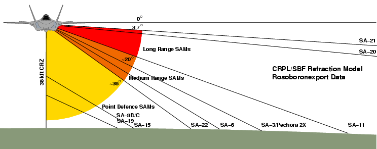
Figure A.3: Threat
depression
angles as a
function of type and missile kinematic range, for various contemporary
and legacy SAMs of Russian/Soviet manufacture (C. Kopp).
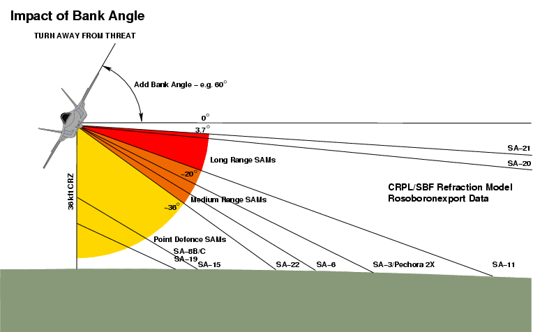
Figure A.4: The impact of bank angles on threat depression angles as a function of type and missile kinematic range, for various contemporary and legacy SAMs of Russian manufacture (C. Kopp).
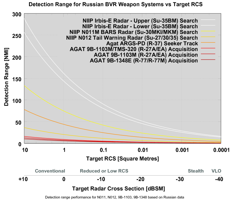
Figure A.5: Performance of
representative Russian fighter radars and missile seekers (C. Kopp).
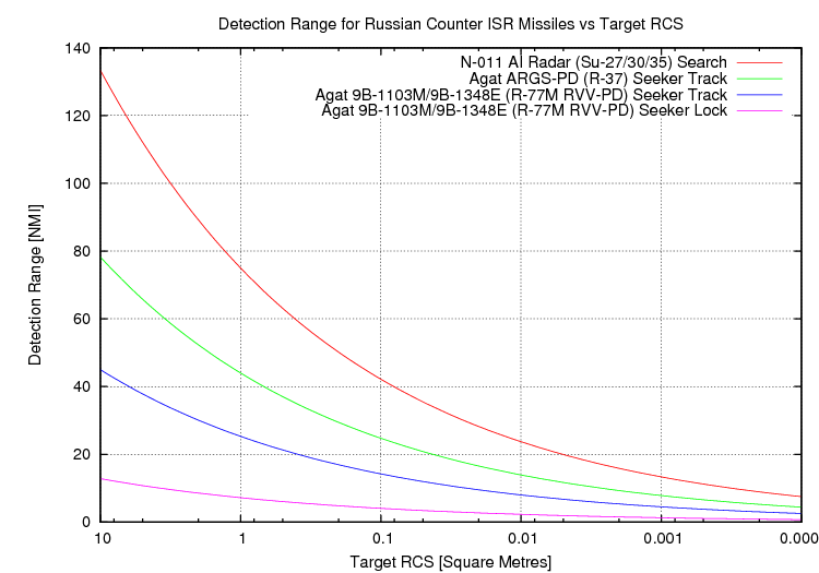
Figure A.6: Performance of representative Russian counter-ISR missile seekers (C. Kopp).
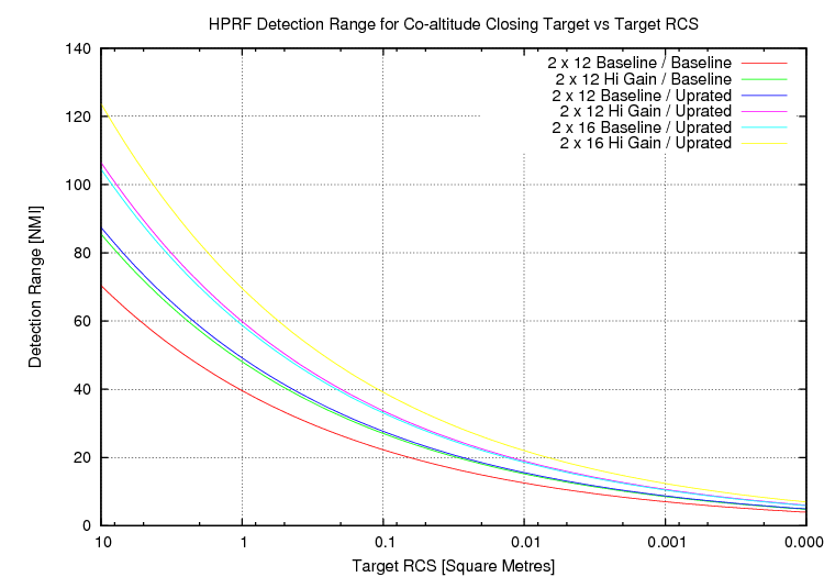
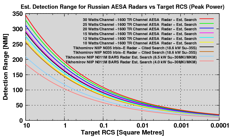
Figure A.7: Performance of NIIP L-Band AESA developed for
Su-30MK/Su-35S (C. Kopp).
Annex B Basic Concepts in Absorbent Coatings Technology
The conventional approach to the design of absorbent coatings for controlling specular reflections is well documented, and good example of the principles is detailed by Kim et al32.
To minimise the reflection of impinging radar signals, the absorbent coating over the aircraft's skin must present an electrical characteristic impedance identical to the air surrounding it, which has an impedance very close to that of free space at 376.730313 Ω, usually approximated as Z0~377 Ω.
For any material to have an impedance of Z0 ≈ 377 Ω, its dielectric permittivity εr and magnetic permeability μr must be very similar in magnitude. This is because:
Z = √ jωμ/(σ + jωε) ; for very small conductivity σ, the impedance can be approximated as Z ≈ √μ/ε, where ω is angular frequency 2πf.If a material has this property and is infinitely thick, the impinging wave will be wholly trapped by the material, without a reflection. The captured wave propagating through the material will be attenuated over distance due to the dielectric and magnetic losses in the material, determined by the complex impedance properties of the material, ε"r and μ"r or the respective material loss tangents taneδ and tanmδ.
If we assume a conductive aircraft skin, such as a metal alloy panel, or structural epoxy composite treated with a conductive coating, or even an untreated structural epoxy composite, covered with an absorbent material coating of finite thickness, the behaviour observed is more complicated.
The wave propagating through the absorber will attenuate with depth, until it hits the impedance discontinuity of the aircraft's skin, where it will reflect. The reflected wave then propagates outward, attenuating with distance, until it hits the boundary between the absorbent coating and air upon which it is reradiated. The magnitude of the reradiated wave is determined by the lossiness of the material, as the wave passes through the material twice.
The attenuation of the wave as it penetrates into the absorber is given by33:
A(d) = A0e-αdTuley employs the term “electrical thickness” to describe the reduction of the wavelength of the penetrating wave as a result of the higher permittivity and permeability of the material, compared to free space, aiding the loss mechanisms34.
where α = – (µ0 ε0)1/2 ω (a2 + b2)1/4 sin [(1/2) tan−1 (–a/b)] and
a = (εr µr – εi µi ) and b = (εr µi – εi µr )
The angle of incidence of the wave will impact absorbing behaviour. At angles other than the broadside case (above) the pathlength through the absorber is necessarily increased, due to basic geometry. In addition, because the absorber is a medium of greater density than air, Snell's Law will apply, and the refractive index n = √μrεr of the material will alter the angle at which the absorber is being penetrated by the wave. In practical terms, an impedance matched absorber coating will perform better at shallower than broadside angles of incidence due to the increased pathlength through the absorber.
The “ideal” absorbent coating for controlling specular reflections would have a Zc ≈ 377 Ω, and be capable of infinitely attenuating all impinging waves at all frequencies of interest in an infinitesimally thin coating. Real materials cannot achieve such performance due to bounds in the magnitude of permittivity, permeability, and loss tangents. Dielectrics and ferrites developed for the electronics industry are indeed typically designed for as low a loss tangent as possible.
A well known difficulty with coatings for controlling specular reflections is in finding materials, or combinations of materials, in which both high permittivities and permeabilities exist, and in which these do not change significantly across a useful band of frequencies, or with environmental conditions, such as temperature.
Dielectric materials with very high permittivities have been developed for electronic component applications, which can be employed to load an epoxy matrix. CNT powders embedded in an epoxy matrix can yield permittivities of ~14.
The principal difficulty arises with the provision of materials to provide high permeability, such as ferrites, as these frequently have high intrinsic permittivities, which subject to the dielectric mixing equation, add in proportion to the permittivity of the epoxy matrix, which is itself typically of the order of εr ≈ 3.0 - 4.6 in the microwave bands, with loss tangents taneδ ≈ 0.01.
This strategy for absorber design is usually termed the “matched characteristic impedance” approach. It is not the only strategy available for achieving an impedance match.
Where the substrate is a material such as a carbon fibre composite panel, which has a complex impedance, the alternative strategy is the choice of a coating or outer panel layer which possesses a complex impedance, such that the combined effect of both layers is an impedance match. This strategy is usually termed the “matched wave impedance” approach35.
Kim et al define the impedance problem in this manner, in terms of impedance mismatch at the air to absorber boundary, where the effective impedance seen by the impinging wave at the air to absorber boundary is determined by the electrical properties of the absorber, its thickness, and the electrical properties of the aircraft skin beneath it. In this instance, an absorber which heavily attenuates the wave produces effective impedance close to Z0, while a less effective absorber exposes the reflection from the aircraft skin, and thus presents as an impedance mismatch at the boundary between the coating and the air.
Yuzcelik includes an example, detailed in Equations 4.27 and 4.2735, for a carbon fibre composite, but the complex permittivity value employed is slightly below measured values32, 35, 37.
Nevertheless, the solution computed by Yuzcelik, Figure 2035, would produce a viable result. Satisfying the necessary equalities for a thin coating will require materials with very high permeability.
In conclusion, the control of specular reflections is only part of a designer's task in applying absorbent materials to an aircraft. Control of edge currents, and surface travelling waves, may require materials with other properties, such as resistive coatings, or strongly magnetic coatings.
Annex C
Axisymmetric Nozzle RCS Performance
The use of axisymmetric nozzles in aircraft intended to have VLO characteristics is a poor design practice. Such nozzles have been employed on the prototypes of the T-50 PAK-FA, J-20, and are intended for the production F-35 configurations.
Axisymmetric nozzles are a direct adaption of the conventional convergent/divergent nozzle designs initially developed during the 1960s to provide a variable nozzle cross-section with an afterburning gas turbine engine. The nozzle shroud is constructed using multiple petals, which slide in the manner of an iris to smoothly change the cross-section of the nozzle aperture, controlled by the engine control system to provide the best aperture for the engine's instantaneous operating conditions.
The RCS of such a nozzle comprises several discrete components36:
- A specular return from the outer shroud of the nozzle, which produces a “doughnut-shaped” symmetrical mainlobe, the peak of which is normal to the face of each petal; the position of the nozzle alters the direction and magnitude of this mainlobe peak;
- A diffractive return from the nozzle aperture rim, approximated as σrim ≈ πr2 where r is the nozzle aperture radius; this return is also rotationally symmetric, but dependent on incident polarisation with the strongest returns resulting from rim components approximately parallel to the electric field.
- A cavity return from the tailpipe of the engine, which
varies with aspect angle and nozzle position, and is often approximated
as σtailpipe
≈ 2πr2
where r is the nozzle aperture radius; random internal bounces
are
assumed.
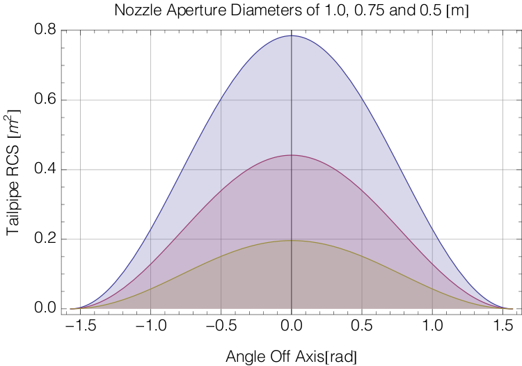
Example untreated tailpipe model, for nozzle aperture diameters of 0.5, 0.75, and 1.0 metres. The angular range depicted is the whole aft hemisphere, with rotational symmetry about the nozzle axis, and a peak RCS from directly behind the aircraft. The resulting magnitudes qualify neither as Very Low Observable or Low Observable, but could be reduced by tailpipe treatments (C Kopp).
Two adaptations have been employed to reduce axisymmetric nozzle RCS in comparison with designs of two decades ago.
The first adaptation is the use of flat petals to form the nozzle shroud segments, removing single or double curvatures. This is intended as a form of faceting, to concentrate the specular return from each petal into a single narrow mainlobe. For typical nozzle dimensions, this technique provides some effect, but only in the upper X-band and Ku/K-bands. Where the wavelength is greater than or comparable to the dimensions of facets, the specular return approximates that of a smooth conical frustrum.
The second adaptation is the use of a serrated nozzle rim, typically using a symmetrical or near symmetrical triangular serration. This technique is also limited in effect to wavelengths where the serration edge length can form a discrete mainlobe. At such frequencies, the serrations produce a conical pattern of discrete narrow mainlobes. For typical nozzle dimensions, this technique provides some effect, but only in the upper X-band and Ku/K-bands. Where the wavelength is greater than or comparable to the dimensions of serrations, the diffractive return approximates that of a smooth circular rim.
The diffractive rim return is an unavoidable byproduct of the axisymmetric nozzle geometry, and in bands where the serrations are ineffective, yields for typical dimensions a return of the order of σrim ≈ 0.5 - 0.8 m2 or -0.9 to -3 dBSM. Such magnitudes qualify neither as Very Low Observable or Low Observable.
In practical terms the axisymmetric nozzle is incompatible with Very Low Observable, or indeed Low Observable, capabilities, and at best yields effects only in the upper bands where active radar homing missile seekers and some missile engagement radars operate. The effect of the shaping adaptations for specular and diffractive rim returns will be that of changing a stable return to a strongly scintillating return. How effective this might be in defeating a missile seeker would depend to a large extent on the design of the seeker and its ability to track such a strongly scintillating return. A more sophisticated seeker would defeat this technique.
The axisymmetric nozzle design is not viable for aircraft intended to penetrate an IADS, as the aircraft will frequently be painted in the aft hemisphere by radars operating across a wide range of bands. In fighter air combat, this strategy is not compatible with any tailchase geometry, as the evading aircraft is pointing its high signature aft hemisphere at the pursuing threat. The survivability of the aircraft will then be determined primarily by the closure rate of the threat, and defaults to the scenarios observed with engagements between aircraft lacking low observability characteristics.
A Physical Optics simulation of the RCS of external shroud of an axisymmetric nozzle was produced to capture the behaviour of the specular component of the nozzle exterior signature. This Physical Optics simulation model does not include a diffractive rim backscatter contribution, or a tailpipe cavity backscatter contribution, both of which are additive to the specular backscatter from the nozzle external skin, and typically dominant from the aft aspects. The observed behaviour in the simulation reflects theoretical predictions for the nozzle very closely.
A strong mainlobe of the order of 12 dBSM is observed at the normal to each petal in the nozzle, with pronounced and periodic axial sidelobes between -8.5 dBSM, -5 dBSM, -1.5 dBSM and 2 dBSM, with angular periodicity reflecting the ratio between feature size and wavelength. Plotted results are in Tables C.1 and C.2.
If we consider -10 dBSM as a reasonable upper bound for compromising the performance of a threat radar in the X-band, the dense sidelobe structure occupies a rotational angular volume from the plane of the nozzle out to almost 45° off the axis of nozzle symmetry.
Behaviour was better in the Ku-band, as the mainlobe and sidelobe width was narrower, concentrating backscatter into a much smaller number of more pronounced lobes.
At S-band and below, the backscatter from overlapping sidelobes forms large regions with strong and stable returns.
A simulation performed using a pair of nozzles separated by a distance identical to that in the J-20 prototype produced an almost identical lobing structure, but with more complex fine structure reflecting in and out of phase additions of backscatter from the respective nozzles.
As noted previously, the overall RCS of the nozzle must also include a tailpipe cavity component, of the order of σtailpipe ≈ 0.5 - 0.8 m2 in magnitude, and a diffractive component produced by the aperture rim, of the order of σrim ≈ 0.5 - 0.8 m2 in magnitude, with a periodic mainlobe and sidelobe structure in the latter forming at wavelengths where serrations produce effect, and rim facets producing discrete specular returns. The Physical Optics simulation indicates that this lobing structure will become prominent at 6 to 8 GHz and above.
The results of the simulation effort validate the theoretical prediction that the axi-symmetric nozzle design does not quality as a Very Low Observable, or indeed Low Observable design in most bands of operational interest.
Table
C.1. Axisymmetric Nozzle Specular RCS Model
Results PEC [V-Pol]
[Click Thumbnail to Enlarge] |
||||||||||
| Frequency |
150 MHz |
600 MHz |
1.2 GHz |
3.0 GHz |
6.0 GHz |
8.0 GHz |
12.0 GHZ |
16.0 GHz |
28.0 GHz |
|
| θ | Φ | PEC Skin [Baseline] |
||||||||
| 090 | 180 | ![J-20-Axisymmetric-Serrated-Nozzle.mdb-00.15GHz-Rs0000-IncPol-TM-Pol-Theta-[E=090.0-A=180.0]](PLA-VLO/Nozzle/J-20-Axisymmetric-Serrated-Nozzle.mdb-00.15GHz-Rs0000-IncPol-TM-Pol-Phi-%5BE=090.0-A=180.0%5D.png "J-20-Axisymmetric-Serrated-Nozzle.mdb-00.15GHz-Rs0000-IncPol-TM-Pol-Theta-[E=090.0-A=180.0]") |
![J-20-Axisymmetric-Serrated-Nozzle.mdb-00.60GHz-Rs0000-IncPol-TM-Pol-Theta-[E=090.0-A=180.0]](PLA-VLO/Nozzle/J-20-Axisymmetric-Serrated-Nozzle.mdb-00.60GHz-Rs0000-IncPol-TM-Pol-Theta-%5BE=090.0-A=180.0%5D.png "J-20-Axisymmetric-Serrated-Nozzle.mdb-00.60GHz-Rs0000-IncPol-TM-Pol-Theta-[E=090.0-A=180.0]") |
![J-20-Axisymmetric-Serrated-Nozzle.mdb-01.20GHz-Rs0000-IncPol-TM-Pol-Theta-[E=090.0-A=180.0]](PLA-VLO/Nozzle/J-20-Axisymmetric-Serrated-Nozzle.mdb-01.20GHz-Rs0000-IncPol-TM-Pol-Theta-%5BE=090.0-A=180.0%5D.png "J-20-Axisymmetric-Serrated-Nozzle.mdb-01.20GHz-Rs0000-IncPol-TM-Pol-Theta-[E=090.0-A=180.0]") |
![J-20-Axisymmetric-Serrated-Nozzle.mdb-03.00GHz-Rs0000-IncPol-TM-Pol-Theta-[E=090.0-A=180.0]](PLA-VLO/Nozzle/J-20-Axisymmetric-Serrated-Nozzle.mdb-03.00GHz-Rs0000-IncPol-TM-Pol-Theta-%5BE=090.0-A=180.0%5D.png "J-20-Axisymmetric-Serrated-Nozzle.mdb-03.00GHz-Rs0000-IncPol-TM-Pol-Theta-[E=090.0-A=180.0]") |
![J-20-Axisymmetric-Serrated-Nozzle.mdb-06.00GHz-Rs0000-IncPol-TM-Pol-Theta-[E=090.0-A=180.0]](PLA-VLO/Nozzle/J-20-Axisymmetric-Serrated-Nozzle.mdb-06.00GHz-Rs0000-IncPol-TM-Pol-Theta-%5BE=090.0-A=180.0%5D.png "J-20-Axisymmetric-Serrated-Nozzle.mdb-06.00GHz-Rs0000-IncPol-TM-Pol-Theta-[E=090.0-A=180.0]") |
![J-20-Axisymmetric-Serrated-Nozzle.mdb-08.00GHz-Rs0000-IncPol-TM-Pol-Theta-[E=090.0-A=180.0]](PLA-VLO/Nozzle/J-20-Axisymmetric-Serrated-Nozzle.mdb-08.00GHz-Rs0000-IncPol-TM-Pol-Theta-%5BE=090.0-A=180.0%5D.png "J-20-Axisymmetric-Serrated-Nozzle.mdb-08.00GHz-Rs0000-IncPol-TM-Pol-Theta-[E=090.0-A=180.0]") |
![J-20-Axisymmetric-Serrated-Nozzle.mdb-12.00GHz-Rs0000-IncPol-TM-Pol-Theta-[E=090.0-A=180.0]](PLA-VLO/Nozzle/J-20-Axisymmetric-Serrated-Nozzle.mdb-12.00GHz-Rs0000-IncPol-TM-Pol-Theta-%5BE=090.0-A=180.0%5D.png "J-20-Axisymmetric-Serrated-Nozzle.mdb-12.00GHz-Rs0000-IncPol-TM-Pol-Theta-[E=090.0-A=180.0]") |
![J-20-Axisymmetric-Serrated-Nozzle.mdb-16.00GHz-Rs0000-IncPol-TM-Pol-Theta-[E=090.0-A=180.0]](PLA-VLO/Nozzle/J-20-Axisymmetric-Serrated-Nozzle.mdb-16.00GHz-Rs0000-IncPol-TM-Pol-Theta-%5BE=090.0-A=180.0%5D.png "J-20-Axisymmetric-Serrated-Nozzle.mdb-16.00GHz-Rs0000-IncPol-TM-Pol-Theta-[E=090.0-A=180.0]") |
![J-20-Axisymmetric-Serrated-Nozzle.mdb-28.00GHz-Rs0000-IncPol-TM-Pol-Theta-[E=090.0-A=180.0]](PLA-VLO/Nozzle/J-20-Axisymmetric-Serrated-Nozzle.mdb-28.00GHz-Rs0000-IncPol-TM-Pol-Theta-%5BE=090.0-A=180.0%5D.png "J-20-Axisymmetric-Serrated-Nozzle.mdb-28.00GHz-Rs0000-IncPol-TM-Pol-Theta-[E=090.0-A=180.0]") |
| 090 | 270 | ![J-20-Axisymmetric-Serrated-Nozzle.mdb-00.15GHz-Rs0000-IncPol-TM-Pol-Theta-[E=090.0-A=270.0]](PLA-VLO/Nozzle/J-20-Axisymmetric-Serrated-Nozzle.mdb-00.15GHz-Rs0000-IncPol-TM-Pol-Theta-%5BE=090.0-A=270.0%5D.png "J-20-Axisymmetric-Serrated-Nozzle.mdb-00.15GHz-Rs0000-IncPol-TM-Pol-Theta-[E=090.0-A=270.0]") |
![J-20-Axisymmetric-Serrated-Nozzle.mdb-00.60GHz-Rs0000-IncPol-TM-Pol-Theta-[E=090.0-A=270.0]](PLA-VLO/Nozzle/J-20-Axisymmetric-Serrated-Nozzle.mdb-00.60GHz-Rs0000-IncPol-TM-Pol-Theta-%5BE=090.0-A=270.0%5D.png "J-20-Axisymmetric-Serrated-Nozzle.mdb-00.60GHz-Rs0000-IncPol-TM-Pol-Theta-[E=090.0-A=270.0]") |
![J-20-Axisymmetric-Serrated-Nozzle.mdb-01.20GHz-Rs0000-IncPol-TM-Pol-Theta-[E=090.0-A=270.0]](PLA-VLO/Nozzle/J-20-Axisymmetric-Serrated-Nozzle.mdb-01.20GHz-Rs0000-IncPol-TM-Pol-Theta-%5BE=090.0-A=270.0%5D.png "J-20-Axisymmetric-Serrated-Nozzle.mdb-01.20GHz-Rs0000-IncPol-TM-Pol-Theta-[E=090.0-A=270.0]") |
![J-20-Axisymmetric-Serrated-Nozzle.mdb-03.00GHz-Rs0000-IncPol-TM-Pol-Theta-[E=090.0-A=270.0]](PLA-VLO/Nozzle/J-20-Axisymmetric-Serrated-Nozzle.mdb-03.00GHz-Rs0000-IncPol-TM-Pol-Theta-%5BE=090.0-A=270.0%5D.png "J-20-Axisymmetric-Serrated-Nozzle.mdb-03.00GHz-Rs0000-IncPol-TM-Pol-Theta-[E=090.0-A=270.0]") |
![J-20-Axisymmetric-Serrated-Nozzle.mdb-06.00GHz-Rs0000-IncPol-TM-Pol-Theta-[E=090.0-A=270.0]](PLA-VLO/Nozzle/J-20-Axisymmetric-Serrated-Nozzle.mdb-06.00GHz-Rs0000-IncPol-TM-Pol-Theta-%5BE=090.0-A=270.0%5D.png "J-20-Axisymmetric-Serrated-Nozzle.mdb-06.00GHz-Rs0000-IncPol-TM-Pol-Theta-[E=090.0-A=270.0]") |
![J-20-Axisymmetric-Serrated-Nozzle.mdb-08.00GHz-Rs0000-IncPol-TM-Pol-Theta-[E=090.0-A=270.0]](PLA-VLO/Nozzle/J-20-Axisymmetric-Serrated-Nozzle.mdb-08.00GHz-Rs0000-IncPol-TM-Pol-Theta-%5BE=090.0-A=270.0%5D.png "J-20-Axisymmetric-Serrated-Nozzle.mdb-08.00GHz-Rs0000-IncPol-TM-Pol-Theta-[E=090.0-A=270.0]") |
![J-20-Axisymmetric-Serrated-Nozzle.mdb-12.00GHz-Rs0000-IncPol-TM-Pol-Theta-[E=090.0-A=270.0]](PLA-VLO/Nozzle/J-20-Axisymmetric-Serrated-Nozzle.mdb-12.00GHz-Rs0000-IncPol-TM-Pol-Theta-%5BE=090.0-A=270.0%5D.png "J-20-Axisymmetric-Serrated-Nozzle.mdb-12.00GHz-Rs0000-IncPol-TM-Pol-Theta-[E=090.0-A=270.0]") |
![J-20-Axisymmetric-Serrated-Nozzle.mdb-16.00GHz-Rs0000-IncPol-TM-Pol-Theta-[E=090.0-A=270.0]](PLA-VLO/Nozzle/J-20-Axisymmetric-Serrated-Nozzle.mdb-16.00GHz-Rs0000-IncPol-TM-Pol-Theta-%5BE=090.0-A=270.0%5D.png "J-20-Axisymmetric-Serrated-Nozzle.mdb-16.00GHz-Rs0000-IncPol-TM-Pol-Theta-[E=090.0-A=270.0]") |
![J-20-Axisymmetric-Serrated-Nozzle.mdb-28.00GHz-Rs0000-IncPol-TM-Pol-Theta-[E=090.0-A=270.0]](PLA-VLO/Nozzle/J-20-Axisymmetric-Serrated-Nozzle.mdb-28.00GHz-Rs0000-IncPol-TM-Pol-Theta-%5BE=090.0-A=270.0%5D.png "J-20-Axisymmetric-Serrated-Nozzle.mdb-28.00GHz-Rs0000-IncPol-TM-Pol-Theta-[E=090.0-A=270.0]") |
| 045 | 225 | ![J-20-Axisymmetric-Serrated-Nozzle.mdb-00.15GHz-Rs0000-IncPol-TM-Pol-Theta-[E=045.0-A=225.0]](PLA-VLO/Nozzle/J-20-Axisymmetric-Serrated-Nozzle.mdb-00.15GHz-Rs0000-IncPol-TM-Pol-Theta-%5BE=045.0-A=225.0%5D.png "J-20-Axisymmetric-Serrated-Nozzle.mdb-00.15GHz-Rs0000-IncPol-TM-Pol-Theta-[E=045.0-A=225.0]") |
![J-20-Axisymmetric-Serrated-Nozzle.mdb-00.60GHz-Rs0000-IncPol-TM-Pol-Theta-[E=045.0-A=225.0]](PLA-VLO/Nozzle/J-20-Axisymmetric-Serrated-Nozzle.mdb-00.60GHz-Rs0000-IncPol-TM-Pol-Theta-%5BE=045.0-A=225.0%5D.png "J-20-Axisymmetric-Serrated-Nozzle.mdb-00.60GHz-Rs0000-IncPol-TM-Pol-Theta-[E=045.0-A=225.0]") |
![J-20-Axisymmetric-Serrated-Nozzle.mdb-01.20GHz-Rs0000-IncPol-TM-Pol-Theta-[E=045.0-A=225.0]](PLA-VLO/Nozzle/J-20-Axisymmetric-Serrated-Nozzle.mdb-01.20GHz-Rs0000-IncPol-TM-Pol-Theta-%5BE=045.0-A=225.0%5D.png "J-20-Axisymmetric-Serrated-Nozzle.mdb-01.20GHz-Rs0000-IncPol-TM-Pol-Theta-[E=045.0-A=225.0]") |
![J-20-Axisymmetric-Serrated-Nozzle.mdb-03.00GHz-Rs0000-IncPol-TM-Pol-Theta-[E=045.0-A=225.0]](PLA-VLO/Nozzle/J-20-Axisymmetric-Serrated-Nozzle.mdb-03.00GHz-Rs0000-IncPol-TM-Pol-Theta-%5BE=045.0-A=225.0%5D.png "J-20-Axisymmetric-Serrated-Nozzle.mdb-03.00GHz-Rs0000-IncPol-TM-Pol-Theta-[E=045.0-A=225.0]") |
![J-20-Axisymmetric-Serrated-Nozzle.mdb-06.00GHz-Rs0000-IncPol-TM-Pol-Theta-[E=045.0-A=225.0]](PLA-VLO/Nozzle/J-20-Axisymmetric-Serrated-Nozzle.mdb-06.00GHz-Rs0000-IncPol-TM-Pol-Theta-%5BE=045.0-A=225.0%5D.png "J-20-Axisymmetric-Serrated-Nozzle.mdb-06.00GHz-Rs0000-IncPol-TM-Pol-Theta-[E=045.0-A=225.0]") |
![J-20-Axisymmetric-Serrated-Nozzle.mdb-08.00GHz-Rs0000-IncPol-TM-Pol-Theta-[E=045.0-A=225.0]](PLA-VLO/Nozzle/J-20-Axisymmetric-Serrated-Nozzle.mdb-08.00GHz-Rs0000-IncPol-TM-Pol-Theta-%5BE=045.0-A=225.0%5D.png "J-20-Axisymmetric-Serrated-Nozzle.mdb-08.00GHz-Rs0000-IncPol-TM-Pol-Theta-[E=045.0-A=225.0]") |
![J-20-Axisymmetric-Serrated-Nozzle.mdb-12.00GHz-Rs0000-IncPol-TM-Pol-Theta-[E=045.0-A=225.0]](PLA-VLO/Nozzle/J-20-Axisymmetric-Serrated-Nozzle.mdb-12.00GHz-Rs0000-IncPol-TM-Pol-Theta-%5BE=045.0-A=225.0%5D.png "J-20-Axisymmetric-Serrated-Nozzle.mdb-12.00GHz-Rs0000-IncPol-TM-Pol-Theta-[E=045.0-A=225.0]") |
![J-20-Axisymmetric-Serrated-Nozzle.mdb-16.00GHz-Rs0000-IncPol-TM-Pol-Theta-[E=045.0-A=225.0]](PLA-VLO/Nozzle/J-20-Axisymmetric-Serrated-Nozzle.mdb-16.00GHz-Rs0000-IncPol-TM-Pol-Theta-%5BE=045.0-A=225.0%5D.png "J-20-Axisymmetric-Serrated-Nozzle.mdb-16.00GHz-Rs0000-IncPol-TM-Pol-Theta-[E=045.0-A=225.0]") |
![J-20-Axisymmetric-Serrated-Nozzle.mdb-28.00GHz-Rs0000-IncPol-TM-Pol-Theta-[E=045.0-A=225.0]](PLA-VLO/Nozzle/J-20-Axisymmetric-Serrated-Nozzle.mdb-28.00GHz-Rs0000-IncPol-TM-Pol-Theta-%5BE=045.0-A=225.0%5D.png "J-20-Axisymmetric-Serrated-Nozzle.mdb-28.00GHz-Rs0000-IncPol-TM-Pol-Theta-[E=045.0-A=225.0]") |
Paired Axisymmetric Nozzle Specular RCS Model Results PEC [V-Pol] |
||||||||||
| 090 | 180 | ![J-20_Axisymmetric_Serrated_Nozzle_[Dual].mdb-00.15GHz-Rs0000-IncPol-TM-Pol-Theta-[E=090.0_A=180.0]](PLA-VLO/Nozzle/J-20_Axisymmetric_Serrated_Nozzle_%5BDual%5D.mdb-00.15GHz-Rs0000-IncPol-TM-Pol-Theta-%5BE=090.0_A=180.0%5D.png "J-20_Axisymmetric_Serrated_Nozzle_[Dual].mdb-00.15GHz-Rs0000-IncPol-TM-Pol-Theta-[E=090.0_A=180.0]") |
![J-20-Axisymmetric-Serrated-Nozzle-[Dual].mdb-00.60GHz-Rs0000-IncPol-TM-Pol-Theta-[E=090.0-A=180.0]](PLA-VLO/Nozzle/J-20-Axisymmetric-Serrated-Nozzle-%5BDual%5D.mdb-00.60GHz-Rs0000-IncPol-TM-Pol-Theta-%5BE=090.0-A=180.0%5D.png "J-20-Axisymmetric-Serrated-Nozzle-[Dual].mdb-00.60GHz-Rs0000-IncPol-TM-Pol-Theta-[E=090.0-A=180.0]") |
![J-20-Axisymmetric-Serrated-Nozzle-[Dual].mdb-01.20GHz-Rs0000-IncPol-TM-Pol-Theta-[E=090.0-A=180.0]](PLA-VLO/Nozzle/J-20-Axisymmetric-Serrated-Nozzle-%5BDual%5D.mdb-01.20GHz-Rs0000-IncPol-TM-Pol-Theta-%5BE=090.0-A=180.0%5D.png "J-20-Axisymmetric-Serrated-Nozzle-[Dual].mdb-01.20GHz-Rs0000-IncPol-TM-Pol-Theta-[E=090.0-A=180.0]") |
![J-20-Axisymmetric-Serrated-Nozzle-[Dual].mdb-03.00GHz-Rs0000-IncPol-TM-Pol-Theta-[E=090.0-A=180.0]](PLA-VLO/Nozzle/J-20-Axisymmetric-Serrated-Nozzle-%5BDual%5D.mdb-03.00GHz-Rs0000-IncPol-TM-Pol-Theta-%5BE=090.0-A=180.0%5D.png "J-20-Axisymmetric-Serrated-Nozzle-[Dual].mdb-03.00GHz-Rs0000-IncPol-TM-Pol-Theta-[E=090.0-A=180.0]") |
![J-20-Axisymmetric-Serrated-Nozzle-[Dual].mdb-06.00GHz-Rs0000-IncPol-TM-Pol-Theta-[E=090.0-A=180.0]](PLA-VLO/Nozzle/J-20-Axisymmetric-Serrated-Nozzle-%5BDual%5D.mdb-06.00GHz-Rs0000-IncPol-TM-Pol-Theta-%5BE=090.0-A=180.0%5D.png "J-20-Axisymmetric-Serrated-Nozzle-[Dual].mdb-06.00GHz-Rs0000-IncPol-TM-Pol-Theta-[E=090.0-A=180.0]") |
![J-20-Axisymmetric-Serrated-Nozzle-[Dual].mdb-08.00GHz-Rs0000-IncPol-TM-Pol-Theta-[E=090.0-A=180.0]](PLA-VLO/Nozzle/J-20-Axisymmetric-Serrated-Nozzle-%5BDual%5D.mdb-08.00GHz-Rs0000-IncPol-TM-Pol-Theta-%5BE=090.0-A=180.0%5D.png "J-20-Axisymmetric-Serrated-Nozzle-[Dual].mdb-08.00GHz-Rs0000-IncPol-TM-Pol-Theta-[E=090.0-A=180.0]") |
![J-20-Axisymmetric-Serrated-Nozzle-[Dual].mdb-12.00GHz-Rs0000-IncPol-TM-Pol-Theta-[E=090.0-A=000.0]](PLA-VLO/Nozzle/J-20-Axisymmetric-Serrated-Nozzle-%5BDual%5D.mdb-12.00GHz-Rs0000-IncPol-TM-Pol-Theta-%5BE=090.0-A=000.0%5D.png "J-20-Axisymmetric-Serrated-Nozzle-[Dual].mdb-12.00GHz-Rs0000-IncPol-TM-Pol-Theta-[E=090.0-A=000.0]") |
![J-20-Axisymmetric-Serrated-Nozzle-[Dual].mdb-16.00GHz-Rs0000-IncPol-TM-Pol-Theta-[E=090.0-A=180.0]](PLA-VLO/Nozzle/J-20-Axisymmetric-Serrated-Nozzle-%5BDual%5D.mdb-16.00GHz-Rs0000-IncPol-TM-Pol-Theta-%5BE=090.0-A=180.0%5D.png "J-20-Axisymmetric-Serrated-Nozzle-[Dual].mdb-16.00GHz-Rs0000-IncPol-TM-Pol-Theta-[E=090.0-A=180.0]") |
![J-20-Axisymmetric-Serrated-Nozzle-[Dual].mdb-28.00GHz-Rs0000-IncPol-TM-Pol-Theta-[E=090.0-A=180.0]](PLA-VLO/Nozzle/J-20-Axisymmetric-Serrated-Nozzle-%5BDual%5D.mdb-28.00GHz-Rs0000-IncPol-TM-Pol-Theta-%5BE=090.0-A=180.0%5D.png "J-20-Axisymmetric-Serrated-Nozzle-[Dual].mdb-28.00GHz-Rs0000-IncPol-TM-Pol-Theta-[E=090.0-A=180.0]") |
|
Table C.2. Axisymmetric Nozzle Specular RCS Model Results PEC [V-Pol] [Click Chart to Enlarge] |
| 150 MHz |
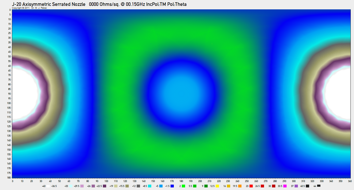 |
| 600 MHz |
 |
| 1.2 GHz |
 |
| 3.0 GHz |
 |
| 6.0 GHz |
 |
| 8.0 GHz |
 |
| 12.0 GHZ |
 |
| 16.0 GHz |
 |
| 28.0 GHz |
 |
| Notes: for angles off
the axis of symmetry between 0° - 80° and 290° - 360°, the dominant
contributions are the specular sidelobes produced by the nozzle petal
shroud skins; the model employed did not include a PEA base.
|
Annex D Viewing RCS Plots
Radar Cross Section plots in this document are represented in two formats, PCSR and PCPR. Both were devised with the intention of providing an easily interpreted graphical representation which can display information with much greater density than the traditional polar plots of RCS.
The use of PCSR and PCPR thus permits a significantly greater volume of data to be presented, compared to polar plots, but with some loss of resolution in magnitude due to the coarse quantisation of the colour scale. This quantisation error is acceptable given the logarithmic scale for RCS magnitude employed.
As this document is published in HTML, it permits easy viewing at a number of resolutions, determined by the browser employed.
All PCSR and PCPR plots are set up with HTML links to the original plots, which are PNG files with respective resolutions of 1000 x 1000 pixels and 1507 x 810 pixels. Clicking on the plot will display it in a user's browser window, or in a separate tab.
Different browsers display PNG graphics differently. Some, like Firefox, Chrome or Safari will initially display the plot scaled to fit the window size. If the window size is smaller than the graphic, clicking on the graphic will enlarge it to its native size on the user display.
It was intended that detailed viewing of PCSR and PCPR plots be performed in the latter fashion, and text font sizes have been set accordingly. A portion of a PCPR plot at native resolution is below.
Annex E Glossary of Terms
- 2D TVC / Two Dimensional Thrust Vector Control: A
TVC arrangement which can control the direction of the engine thrust in
a
single geometrical plane, typically in the pitching axis.
- 3D TVC / Three Dimensional Thrust Vector Control: A TVC arrangement which can control the direction of the engine thrust in two mutually orthogonal geometrical planes.
- AESA: Active Electronically Steered [Scanned]
Array. A phased array antenna in which each element includes a solid
state
transmitter, receiver, and phase or delay beamsteering control
component.
- Azimuth Angles: The angle at which an illuminating
emitter is seen in the plane of flight of the aircraft, relative to
some datum such as the direction of flight.
- CoG / Centre of Gravity: The center of gravity is a
geometric property of any object. The center of gravity is the average
location of the weight of an object [NASA GRC].
- Carbon Nano-Tube (CNT): A CNT is one of eight
allotropes of carbon, where the molecule is formed as a single or
multiple walled tube, the walls of which are formed by connected
hexagonal rings; sometimes CNTs are termed buckytubes.
- CNT/Epoxy Absorbers: A RAM comprising an epoxy resin matrix loaded with Carbon Nanotube powder.
- dBSM: deciBels with reference to a square metre; a
logarithmic measure of RCS computed by multiplying the logarithm to the
base of ten of the RCS in square metres by ten.
- Depression Angle: The angle at which an illuminating emitter is seen below the plane of flight of the aircraft.
- DSI (Diverterless Supersonic Inlet): A DSI is an
inlet configuration where the inboard edge usually employed for
boundary layer control is replaced by a blister shaped protrusion; in
stealth design this is intended to remove the diffractive backscatter
from the inboard inlet leading edge.
- Elevation Angle: The angle at which an illuminating emitter is seen above the plane of flight of the aircraft.
- EO (Electro-Optical) Apertures: a cover usually
intended to protect an electro-optical sensor from the effects of its
physical environment without degrading its optical performance; the
optical mirror or lens system which focusses photons on to an optical
detection device such as an imaging chip.
- Ferrite/Epoxy Absorbers: A RAM comprising an epoxy resin matrix loaded with a ferrite powder.
- Gap Treatment: An absorber material or shaping
arrangement employed to reduce the RCS of a gap between two skin
panels, or a movable surface or door and fixed skin panel.
- Geometrical Diffraction: A method of computing RCS that is an extension of geometric optics that accounts for diffraction [Barton & Leonov].
- Lossy Surface Coating: A type of RAM which is
designed to produce electrical losses, but is not designed to
necessarily suppress specular reflections.
- Low Observable (LO): Early literature: any stealth aircraft; recent literature: a stealth aircraft with limited signature reduction, usually with an RCS between -10 and -30 dBSM.
- Matlab Language: An interpreted computer language
for mathematical expressions used by the Matlab code.
- NPS POFacets Code: A Physical Optics RCS simulator program designed and implemented at the Naval Postgraduate School in Monterey, California.
- Optics Scattering Regime: A scattering regime where the wavelength is smaller or very much smaller than the size of the object or shape scattering the wave.
- Panel Serration: A serration is a repetitive
triangular pattern used along an edge and intended to scatter surface
travelling waves in directions other than the normal to the line of the
edge.
- PCPR Format (PCPR): PolyChromatic Planar Representation (PCPR) is such a representation in which a rectangular area is divided into tiles by aspect angle pair {θ, Φ}. The colour of each tile represents the RCS from the angular direction determined by the path between the tile and the centroid of the aircraft.
- PCSR Format (PCSR): PolyChromatic Spherical Representation (PCSR) is such a representation in which a translucent sphere is rendered around a two-dimensional rendering of the aircraft, where the surface of the sphere is divided into tiles by aspect angle pair {θ, Φ}. The colour of each tile represents the RCS from the angular direction determined by the path between the tile and the centroid of the aircraft.
- Perfect Electrical Absorber (PEA): A material with a
characteristic impedance equal to that of free space and an infinite
loss for all wavelengths of interest.
- Perfect Electrical Conductor (PEC): A material with
a characteristic impedance of zero for all wavelengths of interest; an
idealised conductive metal.
- Physical Optics (PO): A method of computing RCS for
which the local current density at
each point on the illuminated portion of the body is assumed to be identical to the current density that would flow at that point on an infinite tangent plane [Barton & Leonov]. - Phased Array: “array antenna whose beam direction or radiation pattern is controlled primarily by the relative phases of the excitation coefficients of the radiating elements.” [Barton & Leonov].
- Radar Absorber: The term absorber refers to a radar absorbing structure or material (RAS or RAM), the purpose of which is to soak up incident energy and reduce the energy reflected back to the radar [Barton & Leonov].
- Radar Absorbent Materials (RAM): A material, such as
a coating, employed as a radar absorber.
- Radar Absorbent Structures (RAS): A structural component, such as a leading edge, employed as a radar absorber.
- Radar Cross Section (RCS): is “a measure of the reflective strength of a radar target.” The usual notation is σ. It is defined as σ = 4π Ps/Pi, where Ps is the power per unit solid angle scattered in a specific direction and Pi is the power per unit area in a plane wave incident on a scatterer from a specified direction [Barton & Leonov].
- Radome: A radome is “a cover usually intended to
protect an antenna from the effects of its physical environment without
degrading its electrical performance.” [Barton & Leonov].
- Raleigh Scattering Regime: A scattering regime where the wavelength is greater than the size of the object or shape scattering the wave; in Raleigh scattering, the backscatter is proportional to the inverse fourth power of the wavelength σ ∝ λ−4.
- Resonant Scattering Regime: A scattering regime where the wavelength is equal to or similar to the size of the object or shape scattering the wave.
- Specular RCS: RCS produced due to specular
scattering effects only.
- Specular Scattering: Scattering where a mirror-like reflection is produced by the scattering object or shape; usually the wavelength is smaller than the size of the object or shape scattering the wave.
- Thrust Vector Control (TVC): Any gas turbine or
rocket propulsion exhaust nozzle arrangement which permits the
direction of the exhaust efflux and thus thrust to be controlled.
Common arrangements include steerable nozzles, vanes or paddles.
- Very Low Observable (VLO): a stealth aircraft with very good signature reduction, usually with an RCS smaller than -30 dBSM.
Air Power Australia Analyses ISSN 1832-2433
|
|||||||||||||
|
|
|
|
|
|
|
|
||||||
|
|
|
|
|
|
|
|
||||||
 [Click for more ...]") |
|||||||||||||
| Artwork, graphic design, layout and text © 2004 - 2014 Carlo Kopp; Text © 2004 - 2014 Peter Goon; All rights reserved. Recommended browsers. Contact webmaster. Site navigation hints. Current hot topics. | |||||||||||||
|
Site Update
Status:
$Revision: 1.753 $
Site History: Notices
and
Updates / NLA Pandora Archive
|
|||||||||||||
|
|
Tweet | Follow @APA_Updates | |||||||||||
|
|
|||||||||||||
|
|
|||||||||||||