|
||||||||||||||||||||||
 |
||||||||||||||||||||||
 |
 |
 |
 |
 |
 |
 |
 |
|||||||||||||||
 |
 |
 |

|
 |
 |
 |
 |
|||||||||||||||
 [Click for more ...]") |
||||||||||||||||||||||
| Last Updated: Mon Jan 27 11:18:09 UTC 2014 | ||||||||||||||||||||||
|
||||||||||||||||||||||
|
||||||||||||||||||||||
|
||||||||||||||||||||||
|
|
|
|
|
|
|
|
|||||||||||||||
|
|
|
|
|
|
|
|
|||||||||||||||
|
||||||||||||||||||||||
| Last Updated: Mon Jan 27 11:18:09 UTC 2014 | ||||||||||||||||||||||
|
||||||||||||||||||||||
| Design of the S-300P and S-300V Surface-to-Air Missile Systems  |
|||
|
|||
Foreword
David K Barton is one of the United
States' most experienced and accomplished innovators
in radar design and engineering, and has authored many important radar
theory
texts. In 1994 the Microwave Journal published his technical
report covering a range of Russian radar designs, based largely on
interviews
with the original lead designers and architects of these systems. This
valuable work remains to date the most exact, accurate and concise
technical summary of the design rationale for these systems ever
published in the unclassified
domain. By arrangement with the Microwave Journal and David Barton, APA
is pleased to provide this HTML excerpt and the original 1994 work to a
contemporary audience.
David
K.
Barton, The 1993 Moscow Airshow, Special Report, Microwave Journal, May, 1994 [PDF
11.4 MB]
|
|||
| MWJ
Editor's note [1994]: This special report is the result of a
visit by the author to the Moscow 1993 Air Show, which was held from
August 31 to September 5, 1993. The show was held at the military
airfield near Ramenskoye, 50 km east of Moscow. The author was
accompanied by Drs. Alexander Leonov and Sergey Leonov and by Prof.
Alexander A. Lemansky, scientific director of Scientific lndustrial
Corp., ALMAZ, a manufacturer of radar equipment based in Moscow. His
invitation was issued on behalf of the Airshow Organizing Committee by
A. Systzov, vice president of AO AVIAPROM, a joint stock company
headquartered in Moscow. The material contained in this special report
is similar to photos and descriptions in classified documents, but this
is the first time such photos and descriptions have been available to a
general audience. The four-color photos of equipment described in the
report appear as a three-page photo exposition |
|||
64N6 Big Bird Three-Dimensional Surveillance
Radar
54K6E1 Command Post 30N6E1 Fire Control Radar S-300PMU1 (Flap Lid / Tomb Stone) 5N63S/30N6E1 Flap Lid / Tomb Stone Antennas and Feeds SA-10/20 (Grumble/Gargoyle) 48N6E/E1/E2 Missile S-300PMU1 48N6E1 Missile and 5P85SU/DU TEL |
|||
S-300PMU1 (SA-10/20) SystemAt the equipment display, the
SA-10 equipment was toured. The fire control radar (NATO designation
Flap Lid) and the operating positions in the command post vehicle were
exhibited. Data from the three-dimensional surveillance radar
[5N64/64N6E] (Big Bird) were displayed in the vehicle. The horizon
search radar [5N66/76N6] (Clam Shell) was not on display.
|
|||
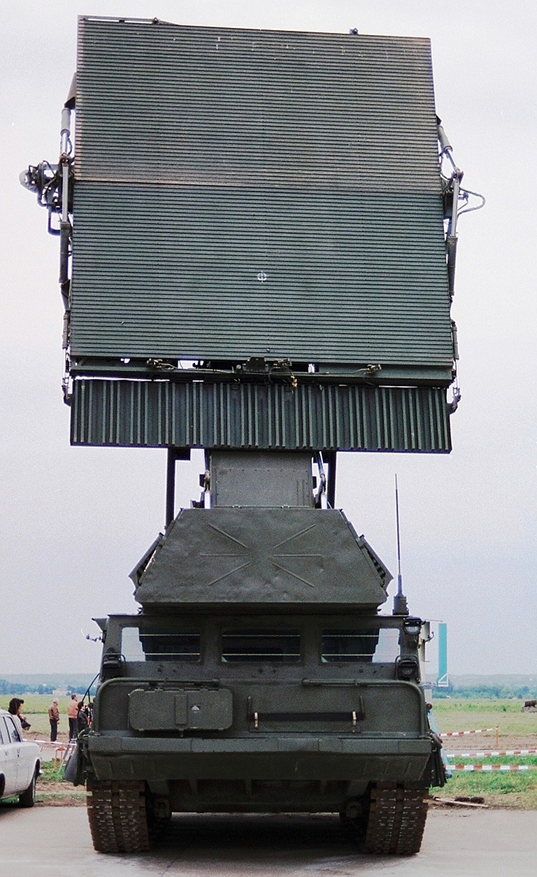
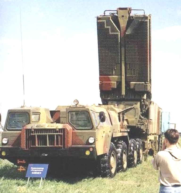
64N6 Big Bird Three-Dimensional Surveillance RadarThe mobile Big Bird on display, is mounted on an eight-wheeled trailer pulled by a large [MAZ79100] prime mover. The antenna is an S-band space fed transmission lens array , fed from both sides by feed horns mounted on a beam passing across the top of the array. The array contains 3400 elements and appears to fold for transport along vertical lines parrallel to the sides of the equipment shelter.The elements are matched to space with what appear to be elongated dielectric bars that are tilted upwards to optimize performance at angles above the horizontal. The search beams, scanning electronically in elevation, lead the array broadside by 30° in azimuth. When a target is detected in a search beam, after a further 29° rotation of the antenna, a backscan is initiated in azimuth to place a validation beam on the elevation and azimuth of the initial detection. lf the detection is repeated in this validation beam, another backscan occurs 180° later in the scan, using the feed horn on the opposite side of the array. Thus, within 210° of rotation following the initial detection, a validation and a second track point are obtained to initiate the track file. From this point on, the track data rate is two points per antenna rotation. The cost of this two-coordinate scanning array may be higher than most Western systems, but the advantages in rapid track initiation and doubled data rate are significant. |
|||
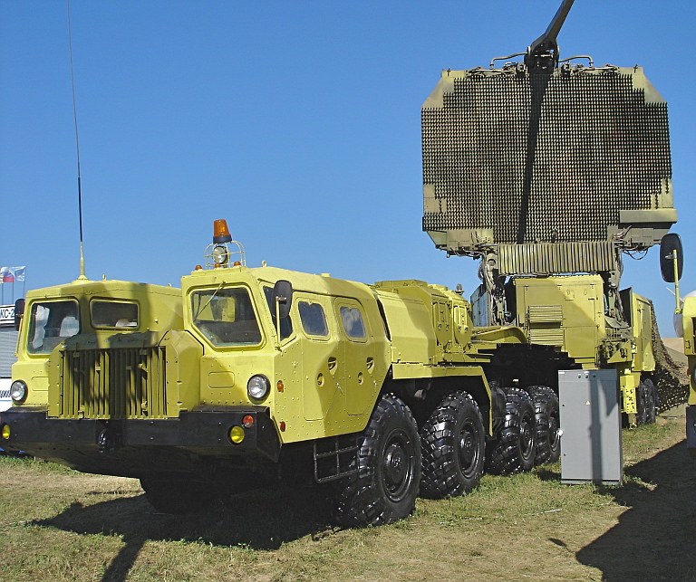 A late model 64N6E2 Big Bird 3D
surveillance radar on display. Below, note the booms and horns feeding
the transmissive array (Wikipedia images).
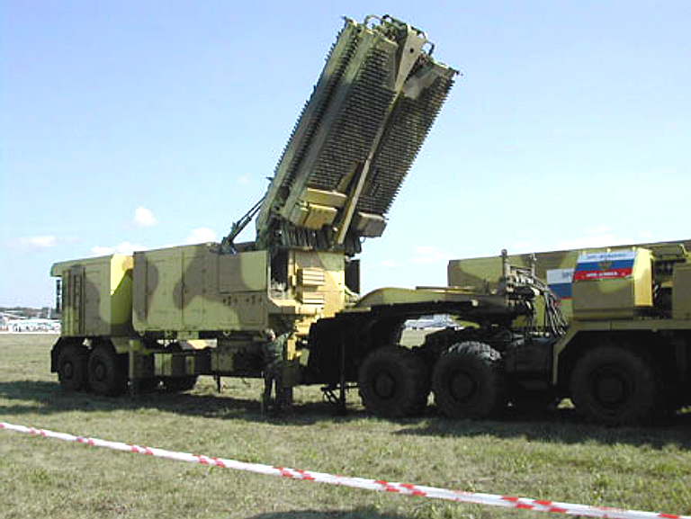
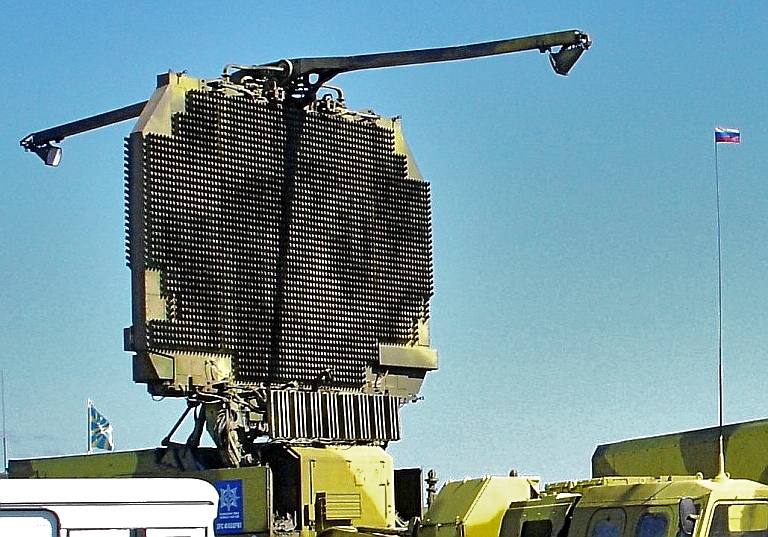  64N6E2 Bid Bird antenna in stowed
position. The outer panels fold inward, the booms carrying the feed
horns fold down flush with the array, and the whole assembly folds
forward and level with the roof of the cabin. Note the waveguides and
rotational couplers feeding the booms. Deploy/stow images here [1], [2] (Russian internet images).
|
|||
54K6E1 Command PostWithin the Command Post (CP)
were five display positions plus positions for communications
personnel. The commander's console was the center of the five consoles,
which were almost identical. Each console had a large plan positioner
indicator (PPI) displaying synthetic video from the Big Bird and from
external sources, as shown in Figures 4 and 5. To the left of the PPI
is an alphanumeric display on which appear the data for up to 36
targets. They are assigned (six each) to the six Flap Lids that may be
controlled by the CP.
To the commander's left, the two positions are occupied by officers who actually fire the missiles. To the right are officers who coordinate with higher headquarters or adjacent CPs, who accept assignments of targets to be passed by the commander to the Flap Lids in priority order, and who evaluate targets detected locally by Big Bird. The small displays at these positions can be set to provide azimuth-elevation (BE) displays of Big Bird video, intensity modulated to show target elevation. The Big Bird data appear on the PPI display as an intensified sweep, leaving behind target markers with alphanumeric tags, which are refreshed at a high rate. |
|||
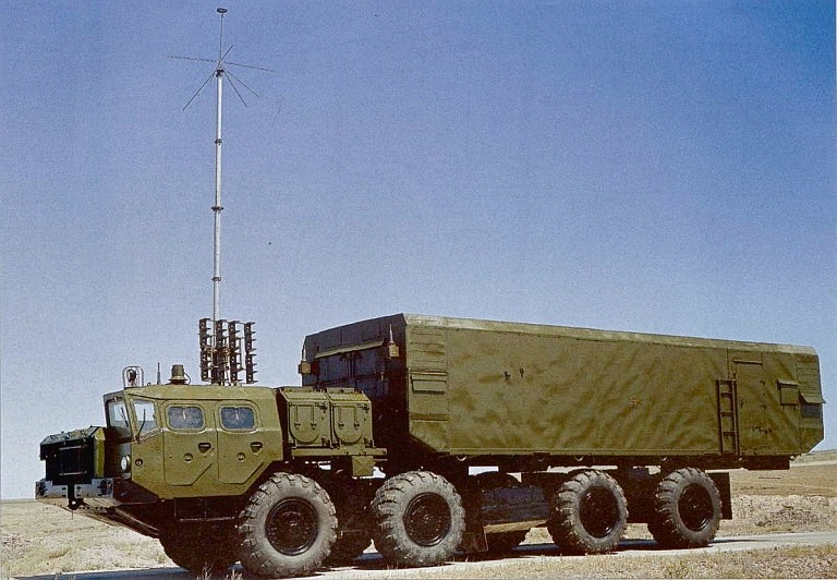 54K6E1
S-300PMU1
Command Post (Russian MoD).
|
|||
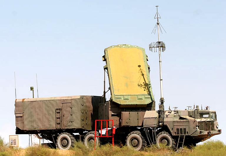 Late model
30N6E1 Tomb Stone in deployed configuration with elevated datalink mast
(Chinese internet image).
|
|||
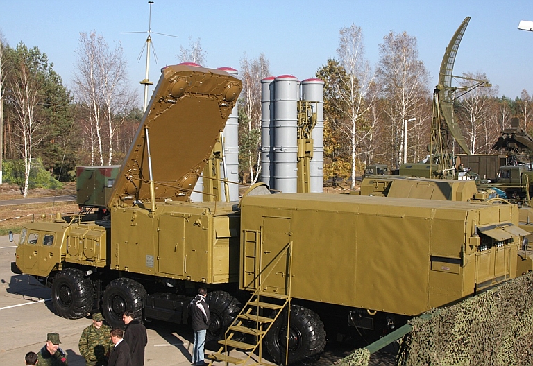
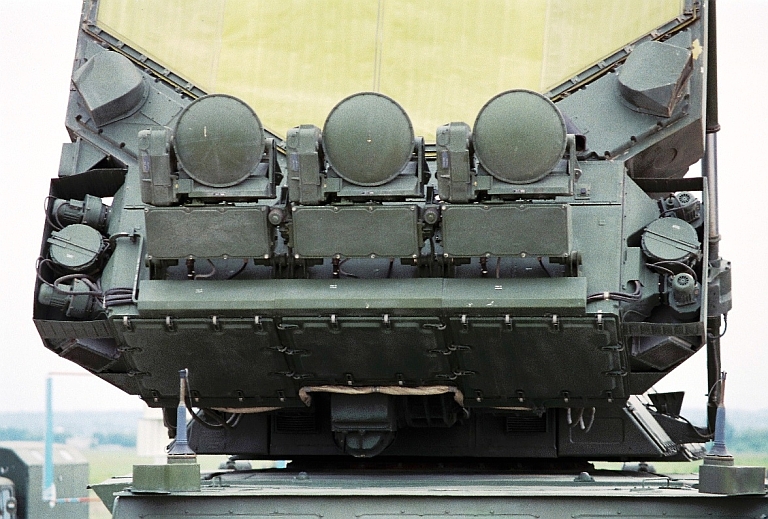
30N6E1 Fire Control Radar S-300PMU1 (Flap Lid / Tomb Stone)The Flap Lid radar tracks up to
six targets that have been assigned by the CP for engagement. The array
is an X-band space-fed lens of 10,000 elements, tilted 30° from the
vertical, as shown in the images. The active portion of the array is
circular, and small sidelobe canceler arrays are within the plastic
cover at the bottom of the main array.
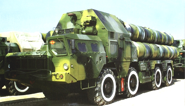
The array is mounted on a
rotatable turret behind the cab of the [MAZ7910] vehicle and in front
of the fixed equipment shelter.
The RF and lF equipment is mounted within the turret, eliminating rotary joints and long runs of waveguide or coaxial cable for receiver signals.  Flap Lid antenna feed
arrangement by David K Barton, original artwork as used in Microwave
Journal, May 1994, provided by author (Image © 1994, 2009 David K
Barton).
 Early model 5N63 Flap Lid towed variant on display at the Moscow District PVO Museum at Zarya, near Moscow. Note the exposed polarisation screen in the space feed (Image © Miroslav Gyűrösi). The feed, shown in the above
image, consists of two linearly polarized horns, a
polarisation-sensitive reflector, and a circular polarizing grid.
The receive horn cluster is on the axis of the array and vertically polarized. The received signal polarisation, which is circular (for example, right-hand) as it passes through the main array, is converted to vertical by the polarizing grid, which is a curved element immediately within the plastic enclosure. The transmit horn is horizontally polarized and is located near the bottom of the plastic enclosure. It illuminates the polarization-sensitive reflector. the plane of which is oriented at about 45- relative to the array axis and which is invisible to the received wave. The polarizing grid transforms the transmitted wave into circular polarization with sense opposite to that of the received wave (for example, left-hand). This transformation provides reciprocal operation of the Faraday rotator phase shifters. The orthogonal polarizations of the transmitted and received waves provide the duplexer isolation normally supplied by a circulator, reducing the round-trip RF loss by 1 dB. Reciprocal operation is an important feature of this array, since the waveform used for target tracking uses bursts at high PRF (100 kHz) to overcome clutter. The clutter attenuation of the system is 100 dB. making possible long range target detection in competition with ground clutter or rain from within the 1500 m unambiguous range of the waveform. As a result of this operating mode, the radar can reject moving clutter from rain, chaff and birds using unambiguous Doppler filtering, as do the continuous wave radars in US systems, such as Hawk. The monopulse receive feed uses six horns. The two center horns are each excited in two modes, one for the sum channel and one for the azimuth difference. Thus, the feed is the equivalent ot the 12-horn feed described by P.W. Hannan in his 1961 paper. Since the received signal is linearly polarized at this feed, multimode operation is possible, and the illumination function can be controlled to minimize sidelobes and spillover.[1] |
|||
5N63S/30N6E1 Flap Lid / Tomb Stone Antennas and Feeds A
late
model
30N6E1
Tomb Stone series engagement radar in deployed position. The
space feed comprises a complex monopulse arrangement, concealed
under a dielectric lens (Images © Miroslav
Gyűrösi).
  30N6E series space feed dielectric lens and collapsible shroud (Images © Miroslav Gyűrösi).   30N6-1 series space feed dielectric lens and collapsible shroud (images © Miroslav Gyűrösi). |
|||
 Early model 5N63S Flap Lid B operated by
the ByeloRussian air defence forces (images © Miroslav
Gyűrösi).
 Note the smaller octagonal array superceded by the rectangular design in the later 30N6 series. 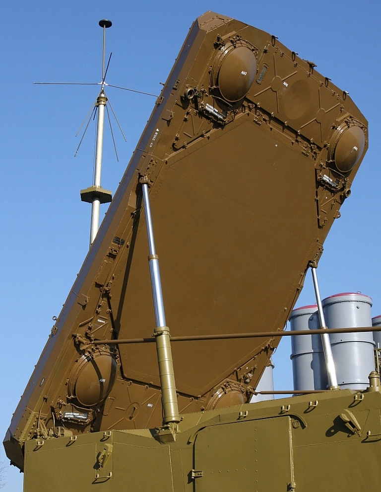  Early model 30N6-1 Flap Lid B/C deployed
in an operational environment. Camouflage netting is used typically to
conceal all fixed components of the installation.
 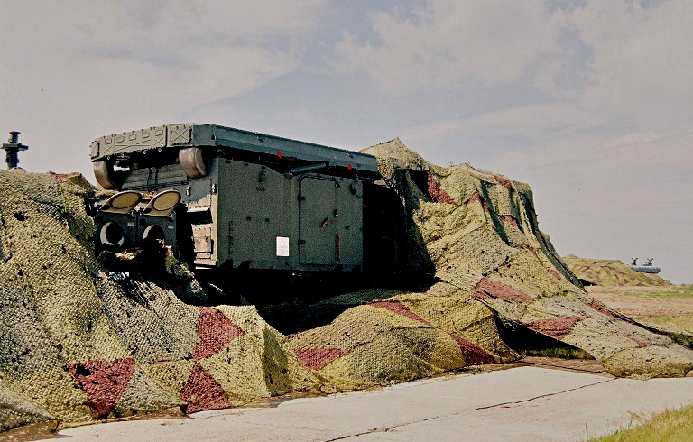 This
image
shows the antennas stowed, and the generator ports open for
operation.
|
|||
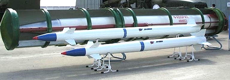
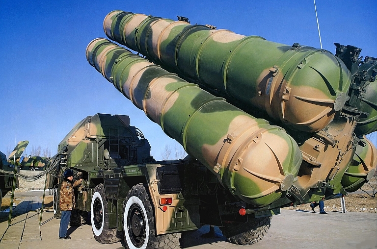
SA-10/20
(Grumble/Gargoyle) 48N6E/E1/E2 Missile
|
|||
|
|
|||
 The 9S32 Grill Pan engagement radar used
with the S-300V/VM / SA-12/23 employs much the same feed arrangement as
the 5N63/63S/30N6E Flap Lid engagement radar used with the
S-300P/PS/PM/PMU/PMU1/2 / SA-10/20 systems (via Smotr).
|
|||
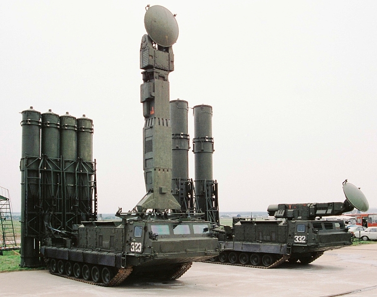
S-300V/VM (SA-12/23) SystemThe SA-12 equipment on display
included the Grill Pan and Bill Board radars, and the missile canisters
and TELARS, shown in images. The High Screen sector search radar for
detection of tactical ballistic missiles (TBM), demonstrated at
Naro-Fominsk July 1993, was not displayed at this show.
|
|||
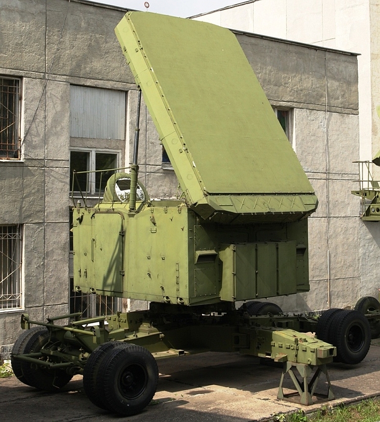
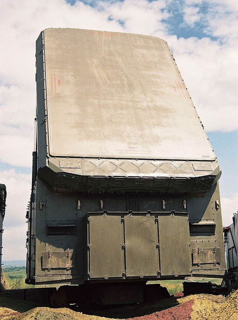
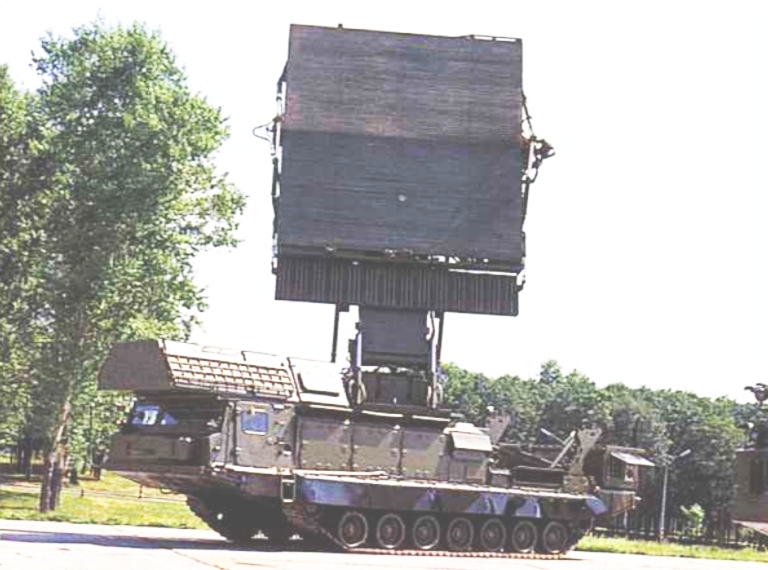
9S15/9S15M/MT Obzor 3 / Bill Board Three-Dimensional Surveillance RadarImages show the Bill Board,
which is an S-band scanning-beam three-dimensional radar using a
phase-scanned planar array of slotted waveguide radiators.
A remarkable feature of this radar is the arrangement for stowing the array for transport. The top of the radar array first folds forward about the hinge at its center to produce a half-height unit. The IFF array folds upwards across the lower front of thi s unit .The entire structure is then folded forward to a 45o angle from the vertical. At this point, the array unit rotates 90o in its aperture plane, reducing the width across the vehicle to match the vehicle width, and the structure continues to fold onto the roof of the vehicle. ln this way, the erected array width can be twice the vehicle width, and the unfolded height can be somewhat greater than the array width. The entire process takes one minute and is carried out by hydraulic pistons with a push button control. |
|||
|
Above 9S15MT
Bill Board (image © Miroslav
Gyűrösi). Additional
images [1], [2]. Below stow operation (via
Smotr).
 |
|||
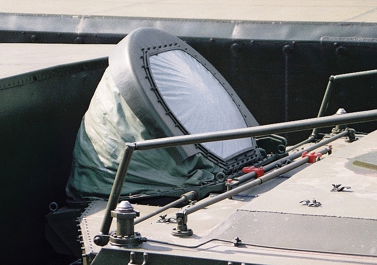
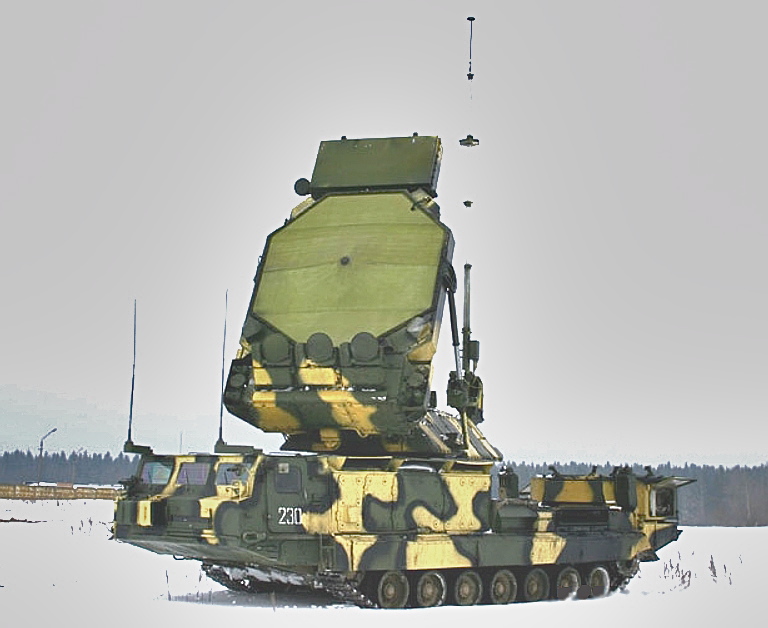
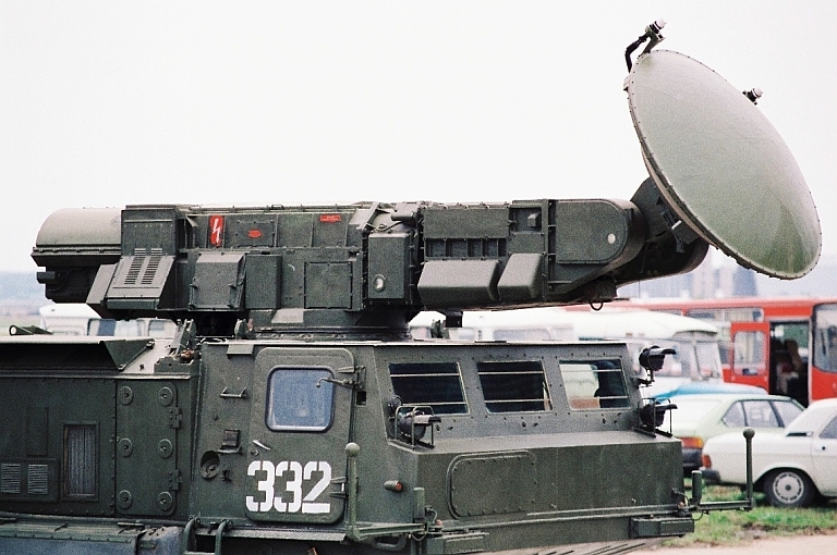
9S32/32M Grill Pan Fire Control RadarEnclosed images show the Grill
Pan, which is a multiple-target X-band tracking and guidance radar
using a 10,000-element space fed transmission lens. Above the radar
array is an IFF planara array, and below it are three sidelobe
canceller antennas, which are mechanically steered to cover the main
array sidelobe structure on up to three selected targets.
There are two monopulse feeds on the top of the rotating radar turret. The upper feed is covered by a white, Teflon-like shell and is used when the array is set to 30° tilt for aircraft targets. The lower feed is further forward on the roof of the turret and is in line with the center axis of the array when it is tilted to approximately 45° for TBM intercepts. The emphasized features of the SA-12 system, including the Grill Pan array, are low RF loss and low cost. The phase shifters are Faraday rotators, having two sections in series, controlled by separate coils, with a total phase of 720°. In each phase shifter, the first coil is connected in series with coils of other phase shifters in that row and driven by the row command. The second coil is connected in series with coils of the other phase shifters in that column and drlven by the corresponding column command. Thus, a 10,000-element array, 100x 100 elements, requires only 100 row drivers and 100 column drivers. There are no electronic components on the phase shifter. The radar transmits right
circular polarization and receives left circular (the predominant
target echo polarization), and hence the Faraday rotator uses the same
control field for reception as for transmission.
The control field is changed
only when the beam position is changed. During a dwell of several
milliseconds, several hundred pulses are transmitted and received. The phase shifter loss is less
than 1 dB in each direction.
Since the transmission and reception are performed with orthogonal polarizations, isolation is obtained with an orthomode feed horn, eliminating the duplexer loss. The low noise receiver (noise factor 3 dB) uses an electrostatic amplifier tube that can withstand leakage powers of several hundred Watts without damage and with near-instantaneous recovery to full gain and sensitivity when the transmitted pulse ends. Thus, the loss attributed to
solid-state protective devices commonly required in Western radars is
also absent.
The total round trip RF loss from transmitter tube to low noise receiver (excluding propagation loss in the atmosphere) is held to 3 dB, in contrast to the 7 to 12 dB found in comparable Western systems. The reduced cost and loss, and
the ability to transmit and process (with high clutter attenuation)
high-PRF waveforms over long dwells, are made possible by the
assignment to the radar of a limited number of tracks and very limited
search capability in, contrast to the Western preference for
multifunction array radars. The cost of separate search radars must be
accepted in such a system. lt is perhaps the reduced emphasis placed by
the Russian military on life-cycle costs of vehicles and personnel that
permits them to use this approach. A
nother possible explanation is the Russian military's insistence on high performance against targets of low cross section in environments containing rain, chaff and other sources of clutter, an almost insoluble problem when the multifunction approach is adopted. |
|||
|
|
|||
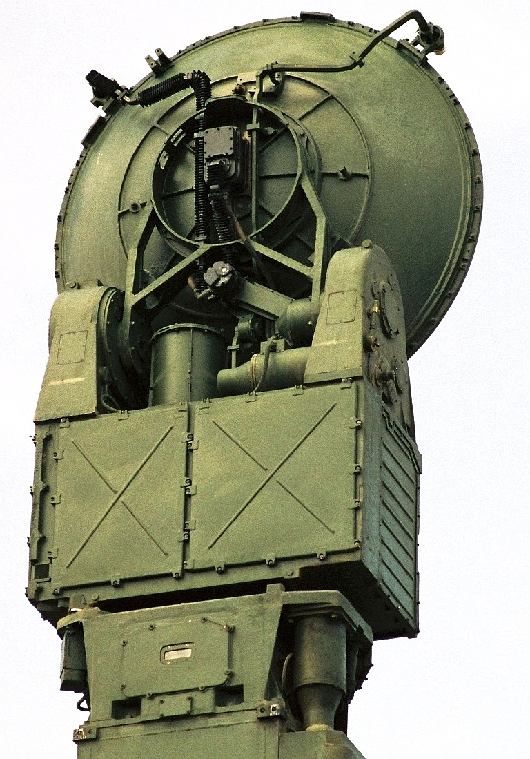
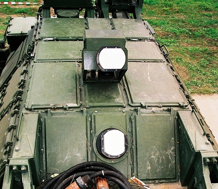 9S32 Grill Pan circular polarised antenna
feeds, the upper is for aircraft targets, the lower for TBM targets.
  |
|||
 9A83
and
9A82 TELARs deployed (images © Miroslav
Gyűrösi).
|
|||
9A82 Giant TELARThe enclosed images show the
TELAR antenna for the Giant missile. The antenna is mounted on a mast
structure that is fixed in a horizontal position. As a result, the
first axis is a roll axis and the second axis, which permits the
antenna to move in elevation, can be an azimuth axis when the first has
rolled through 90°. In effect, the pedestal is of the x-y type, which
can track targets through zenith without excessive angular
accelerations.
|
|||
9A83 Gladiator TELARThe TELAR for the smaller (Gladiator) missile has an antenna mast that is erected vertically, a s shown in exclosed images. The antenna pedestal is the conventional elevation over a zimuth type. There are four missile canisters at the rear of the TELAR, and the bottoms of these c anisters rest on the ground when the canisters are raised to the vertical launch position. |
|||
 9P82
CW
Illuminator antenna in detail.
   9P83 CW Illuminator antenna in detail.  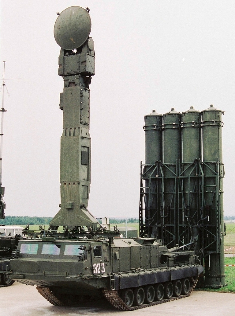 |
|||
Endnotes[1] P.W.Hanna, "Optimum Feeds for All Three Modes of a Monopulse Antenna," IRE Trans. Ant. Propagation,AP-9, No.5 , Sept.1961, pp.444-461. |
|||
The AuthorDavid K. Barton received his AB
degree in physics from Harvard College in 1949. From 1949 to 1984, he
held positions in both government and industry, including Signal Corps.
assignments to White Sands Missile Range and Evans Signal Laboratory,
and positions at RCA and Raytheon Co. Since 1984, Barton has been vice
president for engineering with ANRO Engineering Inc. His work has
included studies of foreign radar technology, as well as consulting in
areas of radar for several major aerospace companies.
In addition, he lectured in radar for the Continuing Engineering Education Program at George Washington University. ln 1958, he was the first recipient of RCA's David W. Sarnoff Award for Outstanding Achievement in Engineering. ln 1961, Barton received the M. Barry Carlton Award of the IRE Professional Group on military electronics. He received the IEEE Centennial Medal in 1984, and during 1987 to 1988 was the distinguished microwave lecturer for the IEEE MTT-9. From 1979 to 1982, he also served on the Air Force Studies Board of the National Academy of Sciences. From 1989 to 1993, Barton was a member of the Air Force Scientific Advisory Board. At present, he is a member of the review board for the Army Research Laboratorv. |
|||
|
|
|||
|
|||||||||||||
|
|
|
|
|
|
|
|
||||||
|
|
|
|
|
|
|
|
||||||
|
|||||||||||||
| Artwork, graphic design, layout and text © 2004 - 2014 Carlo Kopp; Text © 2004 - 2014 Peter Goon; All rights reserved. Recommended browsers. Contact webmaster. Site navigation hints. Current hot topics. | |||||||||||||
|
Site Update
Status:
$Revision: 1.753 $
Site History: Notices
and
Updates / NLA Pandora Archive
|
|||||||||||||
|
|
Tweet | Follow @APA_Updates | |||||||||||
|
|
|||||||||||||
|
|
|||||||||||||


