|
||||||||||||||||||||||
 |
||||||||||||||||||||||
 |
 |
 |
 |
 |
 |
 |
 |
|||||||||||||||
 |
 |
 |

|
 |
 |
 |
 |
|||||||||||||||
 [Click for more ...]") |
||||||||||||||||||||||
| Last Updated: Mon Jan 27 11:18:09 UTC 2014 | ||||||||||||||||||||||
|
||||||||||||||||||||||


|
Wedgetail AEW&C Apertures
|
Technical Report APA-TR-2011-0301 Dr Carlo Kopp, AFAIAA, SMIEEE, PEng 26th March, 2011 Text © 2010, 2011 Carlo Kopp Detail Imagery © 2005 - 2011 Carlo Kopp |

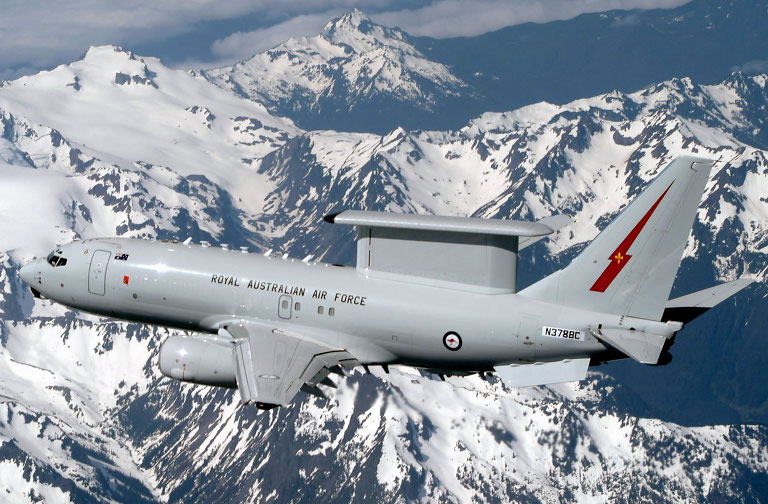
A
pair
of
production
Wedgetail
AEW&C aircraft
(Boeing).
|
IntroductionThe Wedgetail AEW&C “Pocket AWACS” is intended to become
Australia's new airborne surveillance and battle management system. The
author was provided with a tour of the first prototype in 2005. This
presented the opportunity to collect some high quality imagery of the
various antennas installed on the aircraft. Additional imagery was
collected in March, 2011. Photography by the author using a Mamiya M645/1000S
/ 80 mm MF (Fuji RDPIII,
NPC160),
645AFD
/ 80 mm AF (Fuji
Pro
160C), and Fuji HS10
10 Megapixel superzoom. |
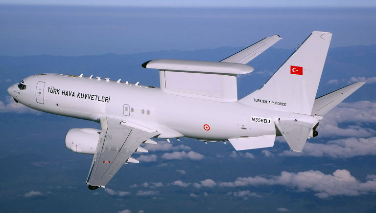
Wedgetail
Apertures
|
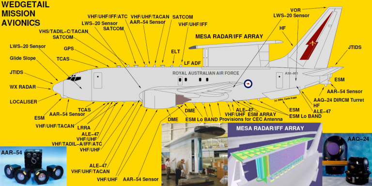 The Wedgetail AEW&C design is based on a hybrid 737 airframe, combining the -600 fuselage and -700/800 wing. The most prominent of the many antenna and optical apertures is the MESA “top hat” AESA antenna subsystem shared between the L-band radar and its integrated IFF system. This design is both innovative but also the principal cause of numerous development problems which resulted in a four year delay against the intended schedule and loss in capability against the initial specification. The dorsal fin mounts the transmit/receive elements for the left and right looking MESA slab arrays. These are a very conventional planar AESA design. The close proximity between the lower edge of the array and upper fuselage presents some problems with coupling between near field lobes and the aircraft structure. The MESA will provide reasonable heightfinding capability as the ~3:1 ratio permits sufficient phase difference across the vertical dimension of the array. The cavity endfire antenna mounted on top of the dorsal fin is intended to provide coverage over the nose and the tail of the aircraft. This design is the first attempt at a production cavity endfire array. It can provide beamsteering in the horizontal plane, generating a vertical fan shaped beam. The internal arrangement is a lower surface with an array of radiating elements, described as a “bed of nails” and a upper surface which is a conventional waveguide arrangement. The design radiates, subject to element phase control, out of the front or the rear openings in the cavity. Public disclosures are insufficient to determine the extent to which the close proximity of the fuselage and tail surfaces impacted performance either by shadowing, near field coupling, or far field reflection1. The MESA radar is supplemented by a variant of the BAe Systems Australia ALR-2001 Odyssey ESM system, based on the Israeli Elta EL/M-8300 (8382) series ESM/ELINT system, which employs a suite of four antenna systems for the microwave bands, mounted under nose, tail and wingtip radomes, and a suite of ventral antennas for the lower bands. Cited EL/M-8300 (8382) performance parameters are a DF accuracy under 1°, instantaneous bandwidth of ~4 GHz, sensitivity between -70 and -85 dBm, and band coverage between 500 MHz and 18 GHz. The production installation may employ optical links for RF signal transmission through the airframe2,3. RF antennas for the extensive C3 suite, covering voice and data channels, are located primarily on the ventral and dorsal fuselage centrelines. Three sets of optical apertures are employed. The AAR-54 MAWS has paired apertures on the nose and tail ESM antenna pedestals, with supplementary dorsal and ventral apertures cited but not validated by imagery. The LWS-20 laser warning system has individual apertures provisioned for along the fuselage - the status of the installation has not been disclosed. Finally the AAQ-24 DIRCM has a reserved location under the tail ESM antenna fairing, but this device has yet to be observed installed on the aircraft. |
Wedgetail Program 2005 - 2011 |
 Wedgetail
AEW&C
prototype
in
2005
(Boeing).
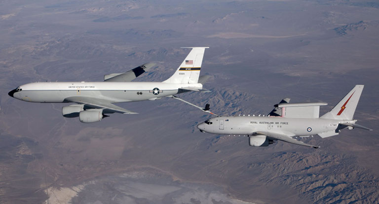 Wedgetail AEW&C prototype performing AAR tests with KC-135R (Boeing). 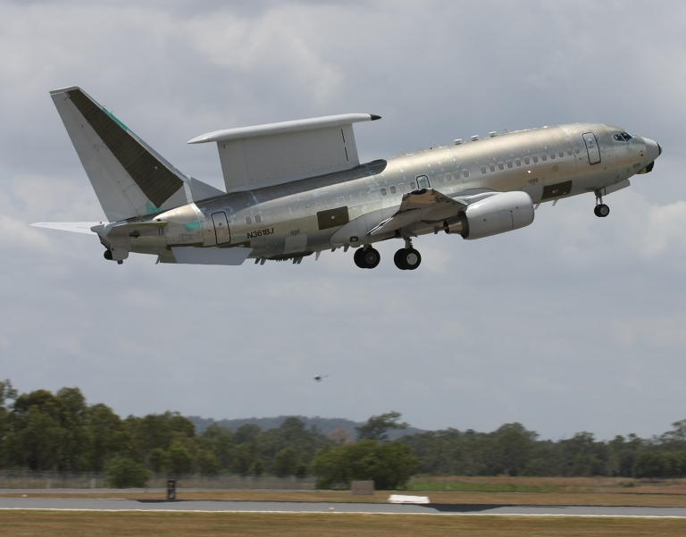 Production Wedgetail with systems
fit at Amberley facility in 2009 (Boeing).
 Above,
below:
Turkish
Wedgetail
AEW&C
(Boeing).
 |
Wedgetail AEW&C Prototype in 2005 |
 Head on view of the first prototype (Author; M645/1000S). 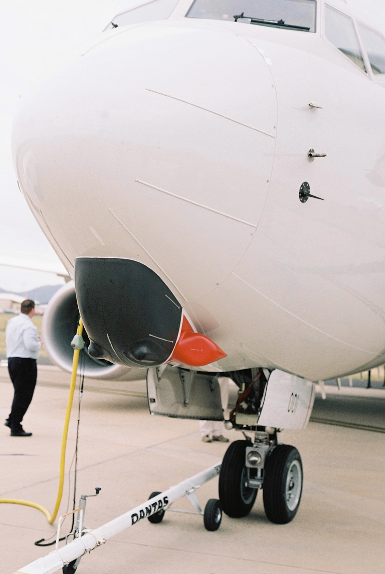 Ventral
nose ESM antenna radome assembly. Note the red covers over the AAR-54
MAWS apertures
(Author; M645/1000S).
|
 Profile view of nose radomes. Note the
circular LWS-20 laser warning receiver aperture below the aft cockpit
window (Author;
M645/1000S).
|
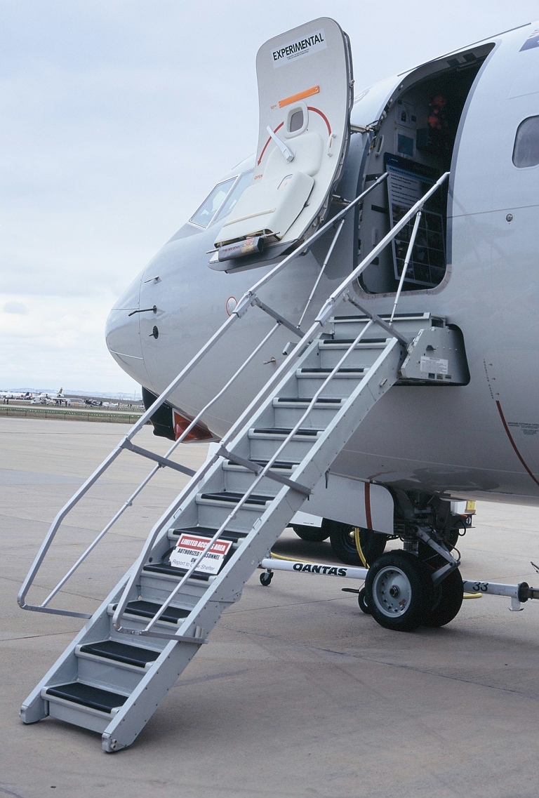 Internally stowed crew access airstairs (Author; M645/1000S). |
 Ventral view of wing and CFM-56 engine, with slats and flaps deployed (Author; M645/1000S). |
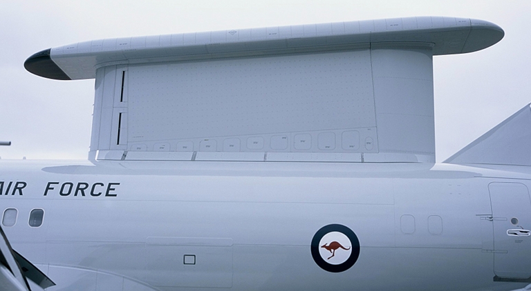
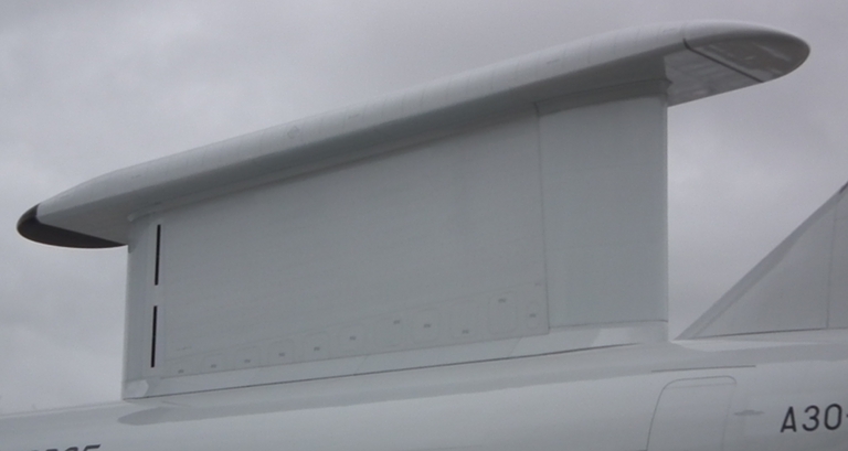
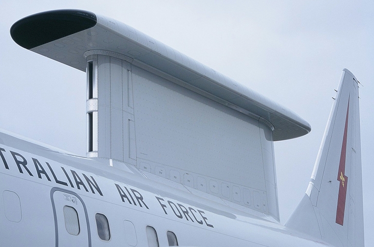 Above, below: Northrop-Grumman MESA L-band
AESA primary antennas. The sidelooking slab arrays provide beam aspect
azimuth, range and heightfinding capability. The dorsal “surfboard”
antenna provides coverage over the nose an tail sectors. Note the dual
air inlets in the leading edge employed for cooling (Author; M645/1000S).
|
 |
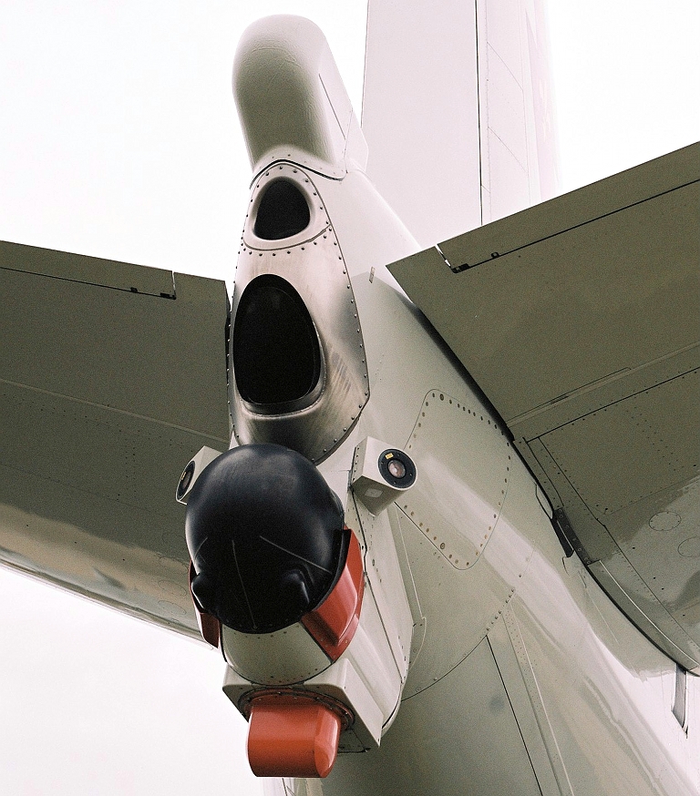
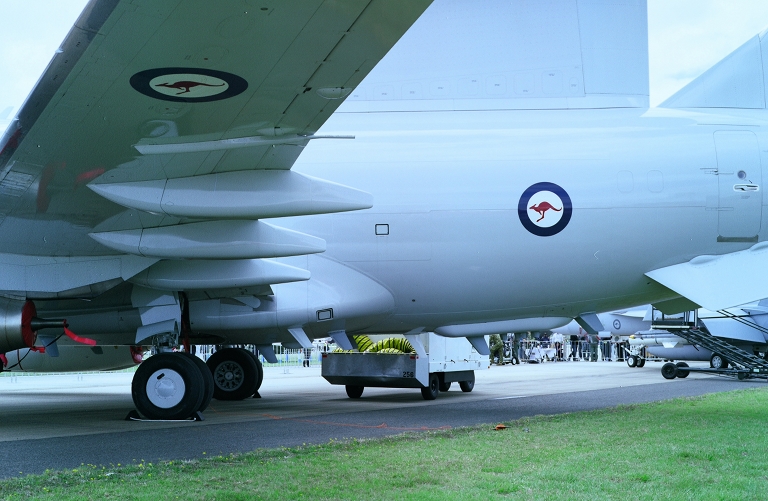
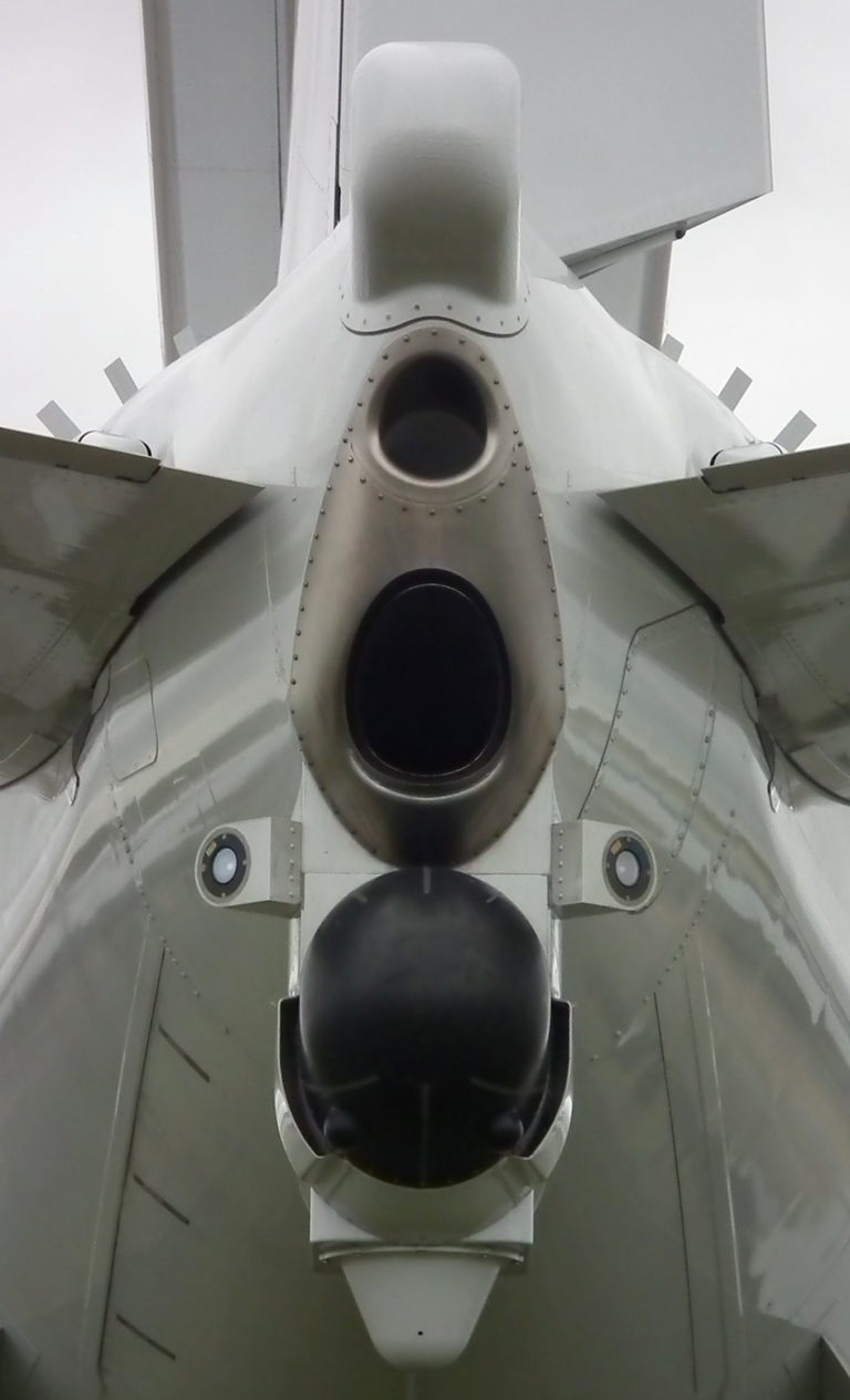
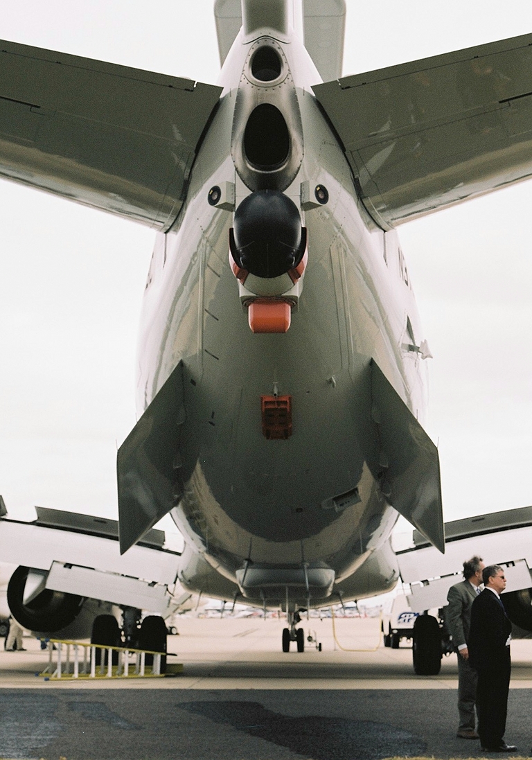 Above, below: aft tailcone fairing
mounting MIDS/JTIDS/Link-16, AN/AAR-54 MAWS, ALR-2001 ESM apertures and
the ventral dummy AN/AAQ-24 DIRCM turret. The AN/ALE-47 CMDS is located
between the ventral strakes (Author; M645/1000S).
|
 |
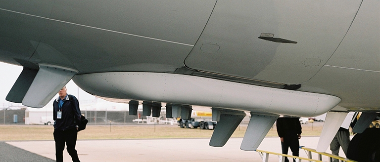 Aft
ventral
centre fuselage showing ALR-2001 low band antenna array (Author; M645/1000S).
|
 Aft
ventral
centre fuselage showing ALR-2001 low band antenna array.
|
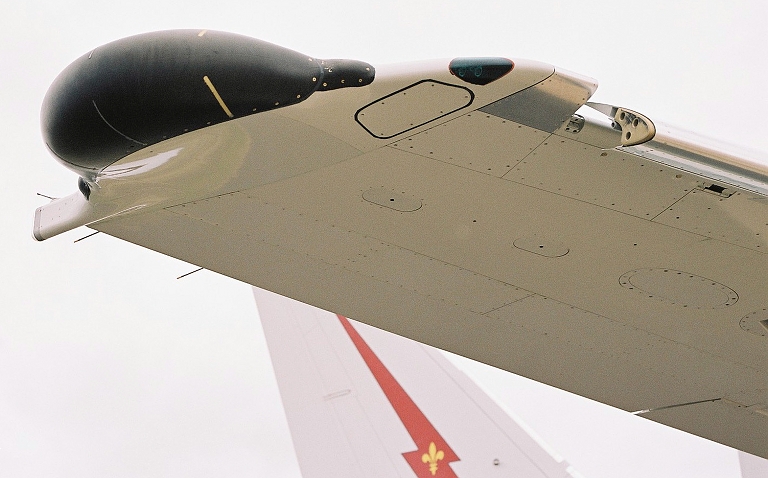 Wingtip
ALR-2001
ESM
array (Author;
M645/1000S).
|
2
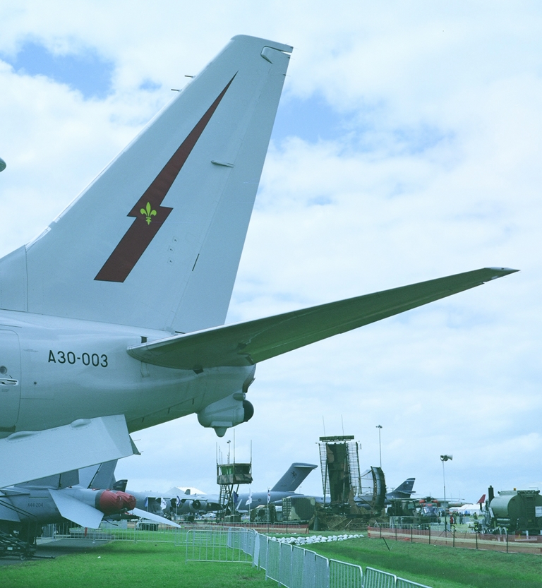
SQN Wedgetail AEW&C A30-003 in 2011
|
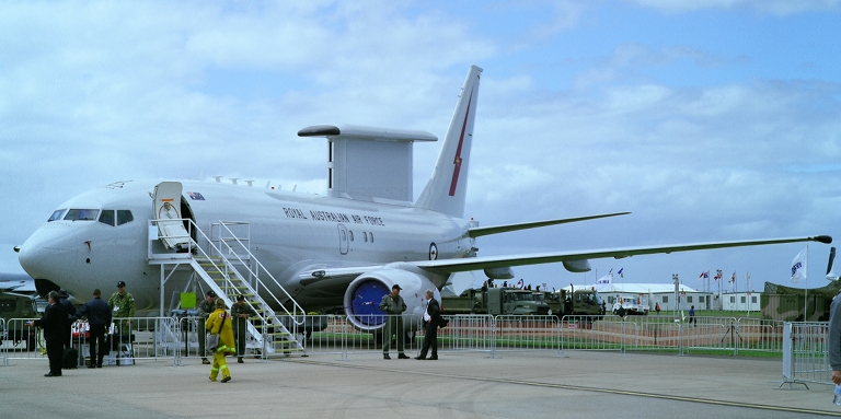 A30-003 Wedgetail AEW&C at
Avalon, 2011
(Author; 645AFD).
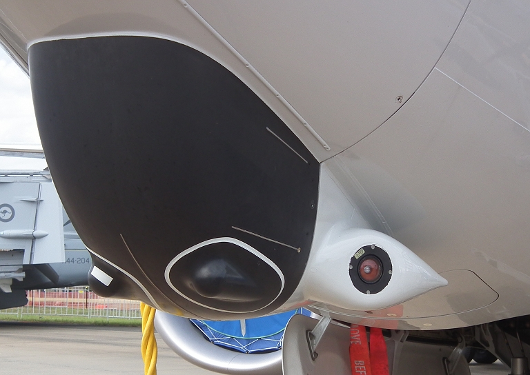 Ventral
nose ESM antenna radome assembly with exposed AAR-54
MAWS apertures
(Author; HS10).
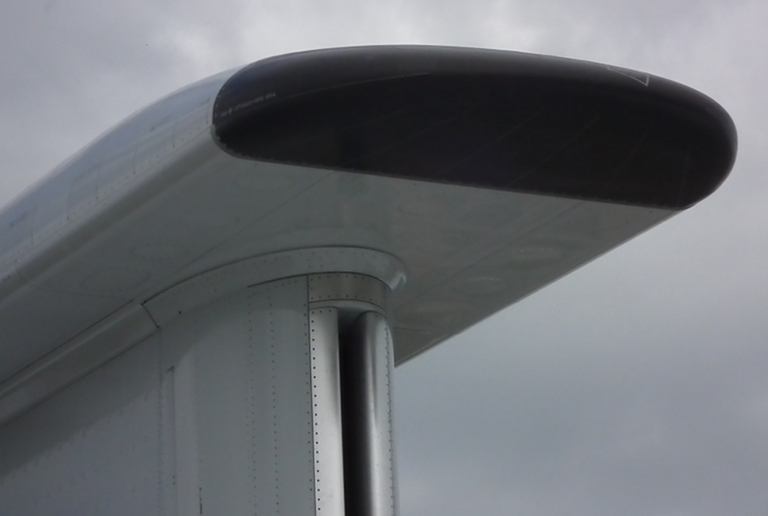
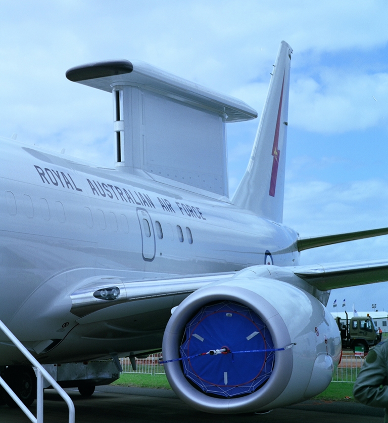 Above, below: Northrop-Grumman
MESA L-band AESA primary antennas. The cavity endfire is in the upper
“surfboard”, and the sidelooking arrays in the vertical fin (Author; 645AFD; below HS10).
 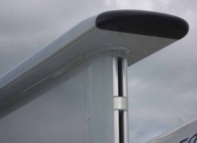 Above, below: Northrop-Grumman MESA
L-band AESA cavity endfire radome (Author; HS10).
  Ventral antennas for C3 system (Author; 645AFD).
 Aft
ventral fuselage showing C3 and ALR-2001 low band antenna arrays (Author; 645AFD).
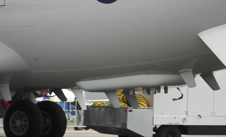 Aft
ventral
centre fuselage showing ALR-2001 low band antenna array (Author; HS10).
 Aft
tailcone fairing installed for antenna placement (Author; above 645AFD, below HS10).
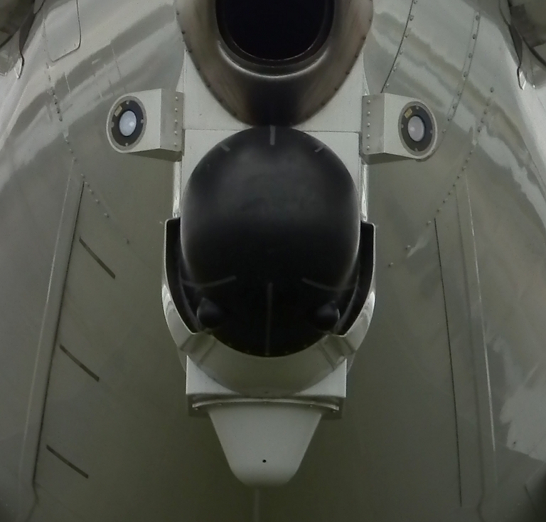
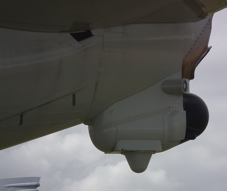 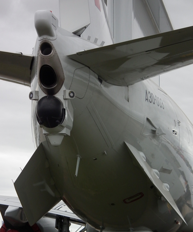 Above,
below:
aft
tailcone
fairing
mounting
MIDS/JTIDS/Link-16, AN/AAR-54 MAWS, ALR-2001 ESM apertures and
the conical ventral fairing replacing the AN/AAQ-24 DIRCM turret (Author; HS10).
  |
Notes / References
|
Annex
A
Boeing
E-3C
AWACS Apertures
|
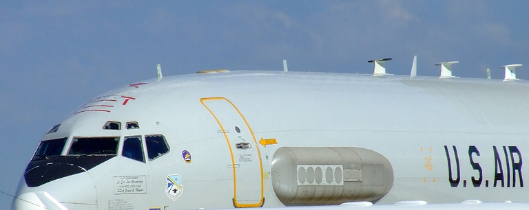
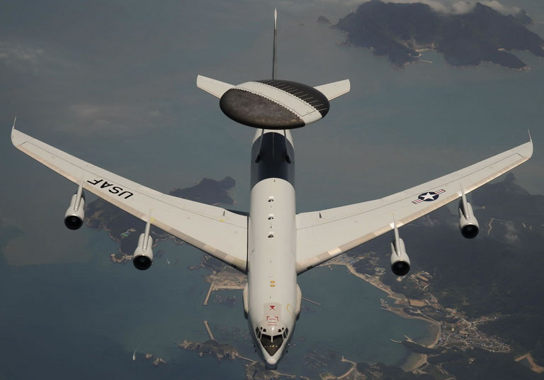 Above,
below:
Boeing
E-3C
Sentry AWACS. Note the forward looking AN/AYR-1
ESM
radome
and
fairing
(US DoD).
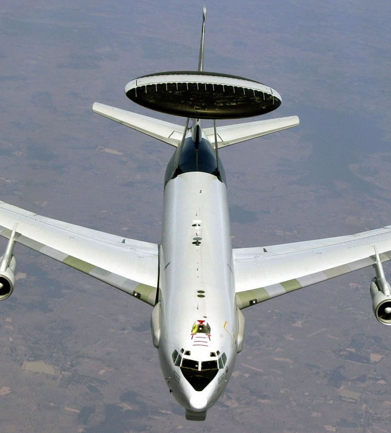 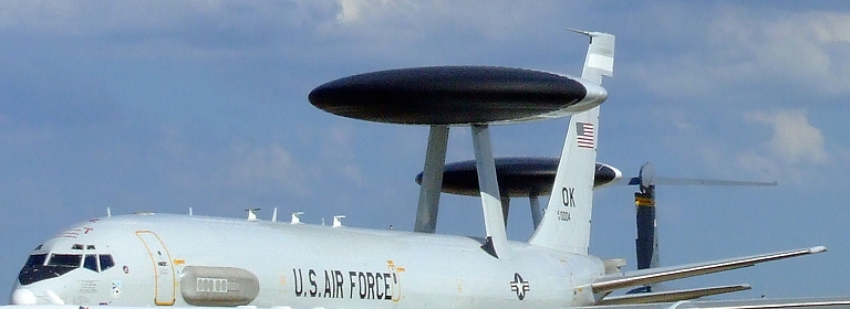 A US
Air
Force E-3C AWACS visiting Australia in 2007. The recently installed
AN/AYR-1 ESM
arrays are prominent, with beam and aft fairings visible. It uses
a dual baseline interferometry scheme for
precision DF.
 |
Annex
B
Boeing
E-3D
AWACS Apertures
|
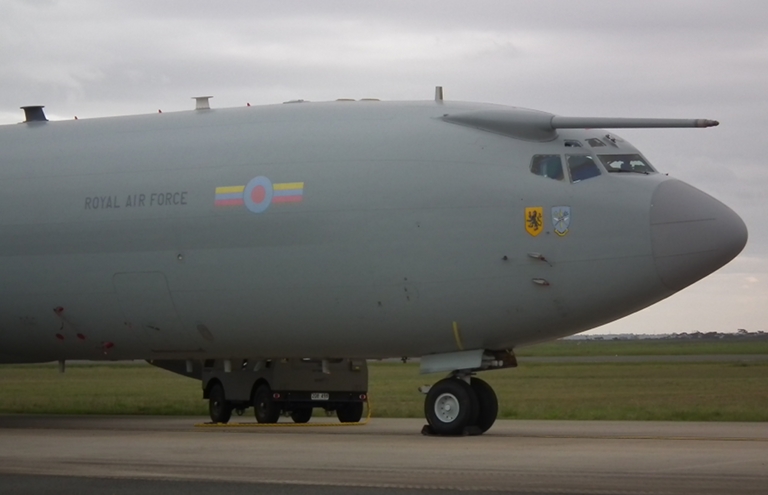
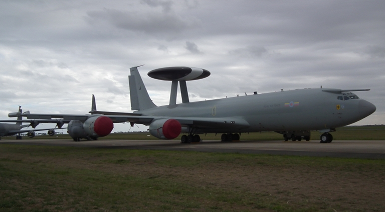 Above, below: Royal Air Force E-3D
Sentry AEW.1 ZH107 at Avalon in March, 2011 (Author; HS10).
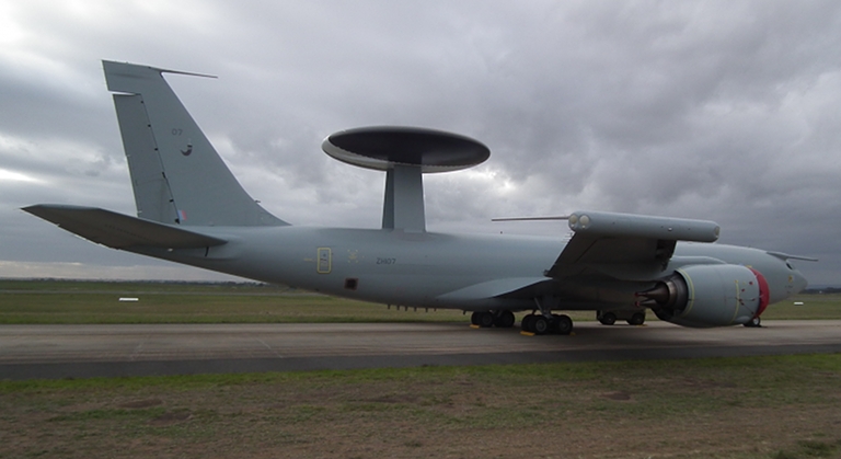  Royal Air Force E-3D Sentry AEW.1
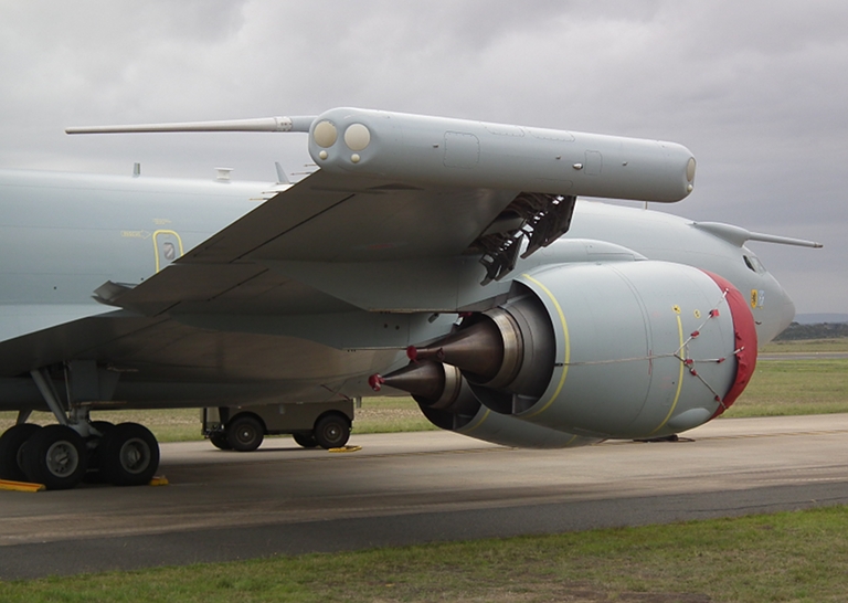
aerial refuelling probe (Author; HS10).
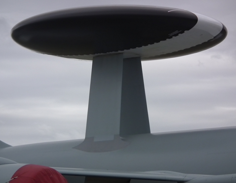
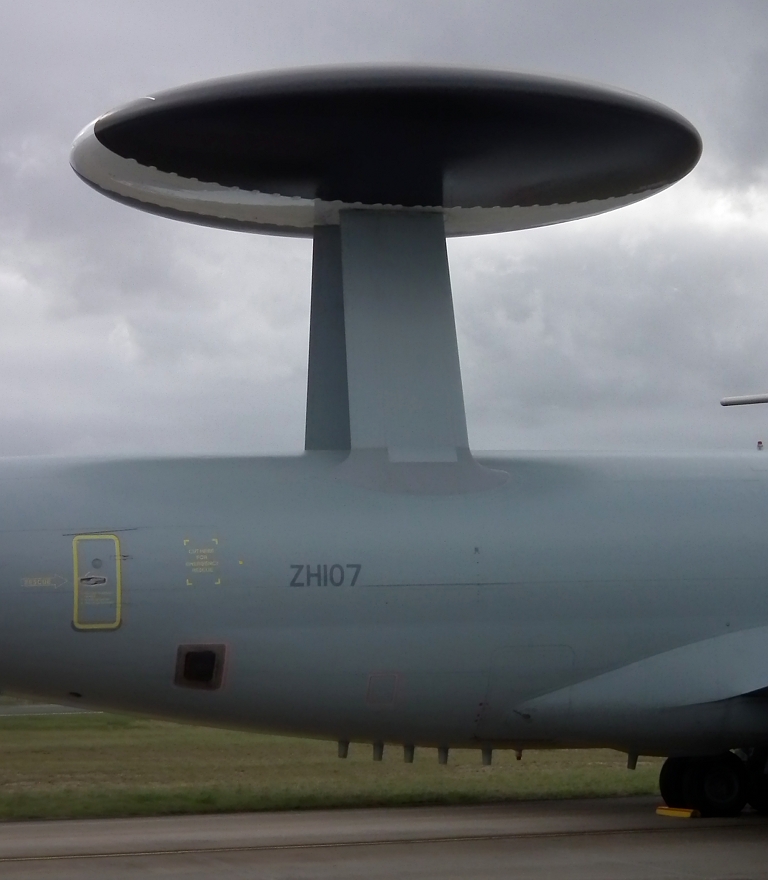 Westinghouse (Northrop-Grumman)
APY-2 rotodome
(Author; HS10).
 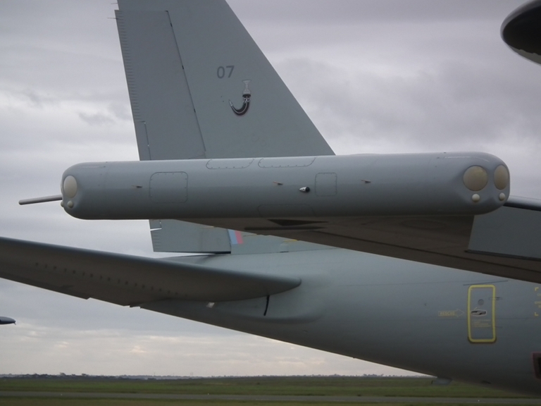 Above, below: Racal/Thorn / Loral
1017 Yellow Gate ESM pod (Author; HS10).
 |
Annex C Boeing E-3F AWACS Apertures |
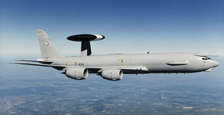 The
Boeing E-3F AWACS shares the AAR probe of the E-3D with the ESM
arrangement of the E-3C (French AF).
|
|
|
|
Technical Report APA-TR-2011-0301 |
|
|||||||||||||
|
|
|
|
|
|
|
|
||||||
|
|
|
|
|
|
|
|
||||||
|
|||||||||||||
| Artwork, graphic design, layout and text © 2004 - 2014 Carlo Kopp; Text © 2004 - 2014 Peter Goon; All rights reserved. Recommended browsers. Contact webmaster. Site navigation hints. Current hot topics. | |||||||||||||
|
Site Update
Status:
$Revision: 1.753 $
Site History: Notices
and
Updates / NLA Pandora Archive
|
|||||||||||||
|
|
Tweet | Follow @APA_Updates | |||||||||||
|
|
|||||||||||||
|
|
|||||||||||||