|
||||||||||||||||||||||
 |
||||||||||||||||||||||
 |
 |
 |
 |
 |
 |
 |
 |
|||||||||||||||
 |
 |
 |

|
 |
 |
 |
 |
|||||||||||||||
 [Click for more ...]") |
||||||||||||||||||||||
| Last Updated: Mon Jan 27 11:18:09 UTC 2014 | ||||||||||||||||||||||
|
||||||||||||||||||||||
|
||||||||||||||||||||||
|
||||||||||||||||||||||
|
|
|
|
|
|
|
|
|||||||||||||||
|
|
|
|
|
|
|
|
|||||||||||||||
|
||||||||||||||||||||||
| Last Updated: Mon Jan 27 11:18:09 UTC 2014 | ||||||||||||||||||||||
|
||||||||||||||||||||||
| APA
Mirror - US Air Force Air & Space Power Journal - Chronicles |
||
| |
||
|
Air & Space Power Chronicles - Chronicles
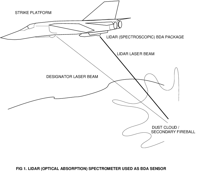
Online Journal Laser Remote Sensing - A New Tool for Air WarfareCarlo Kopp1. IntroductionLaser Remote Sensing techniques are an established and mature scientific method used extensively in civilian research such as environmental monitoring and atmospheric research. This paper discusses specific problems inherent with established technologies applied to Reconnaissance, Surveillance and Bomb Damage Assessment, and proposes specific applications for Laser Remote Sensing methods, which resolve the ambiguities which may result from the use of established Reconnaissance, Surveillance and Bomb Damage Assessment sensors. 2. The Limitations of Contemporary Optical BDA and Reconnaissance MethodsBomb Damage Assessment (BDA) has historically been a task of considerable difficulty because the wide range of munitions utilised, target types attacked and modes of attack used have precluded the application of any single reliable method. The only wholly reliable method of Bomb Damage Assessment to date has been to overrun the target with friendly land forces, and examine the damage inflicted by the air attack. This is not a practical proposition in most wartime situations, as the target may not be readily accessible, or it may be heavily defended by hostile land forces. An alternative is to deploy Special Operations Forces to observe the target from shorter distances, however this method is problematic as it uses a scarce wartime resource. Air Forces have traditionally relied upon photographic evidence to assess the damage inflicted upon the target. The photography may be carried out by the delivery aircraft with an onboard Bomb Damage Assessment camera, or by a post strike reconnaissance sortie flown by another aircraft. The latter has the advantage of potentially cleaner photography due to the absence of smoke and dust clouds produced by the delivered munitions, as well as better quality imagery due the use of specialised reconnaissance camera equipment. Photography as a method for assessing bomb damage has its limitations. Static single frame images, using single aperture or stereoscopic photography, will suffer limitations in resolution due the film medium and camera's performance, as well as being unable to provide clear definition through haze, cloud, smoke or other obscurants. A clever opponent may successfully defeat conventional photographic reconnaissance by using smoke generators, camouflage or decoys with suitable accuracy in shape, size and contrast. Thermal Imaging or Infra-Red photography, using either FLIR (Forward Looking Infra-Red) equipment, or purpose designed reconnaissance linescan cameras, has provided some notable gains over conventional photographic methods of Bomb Damage Assessment. A Thermal Imager will register temperature differences in a target with contrast, or subject to postprocessing, false colour. Infrared radiation will also penetrate many obscurant aerosols far better than visible wavelengths, as the wavelengths are larger in relation to the aerosol particles in the atmosphere. The advent of Thermal Imaging (FLIR) targeting systems such as Pave Tack and LANTIRN has added a new aspect to conventional Bomb Damage Assessment. These systems use a Thermal Imaging camera boresighted with a near InfraRed pulsed laser (typically 1.066 um Nd:YAG). The laser is used both for rangefinding and designation of targets with a coded pulse stream, for use by laser guided munitions. If the thermal imagery is fed into a video tape recording device, a real time record of the attack will exist for post flight analysis. This feature of the F-111F Pave Tack and F-117A DLIR was used extensively for BDA during the Gulf Campaign. The limitation of both photographic and thermal imaging methods is that they can only provide contrast information in the visible and InfraRed bands. While this is suitable for Bomb Damage Assessment and identification of many target types, it may not be adequate for assessing hardened targets or targets housed in hardened facilities. A very good example are bunkers used as command posts, and hardened aircraft shelters concealing aircraft. The Desert Storm air campaign is a good instance of this problem, in that many such targets were needlessly reattacked due to inadequate BDA. A thermal imagery tape of an attack on such a target may reveal that the delivered weapon has successfully penetrated into the hardened shelter and detonated inside. The overpressure of thousands of psi inside the shelter will have forced open doors, hatches and vents, and this will have been visible in the taped imagery. It is therefore reasonable to assume that equipment and personnel inside the hardened shelter will have perished. However it is not possible to determine from such evidence whether the shelter contained either equipment or personnel. Only in the event that fuel or munitions of sufficient quantity were contained within the shelter to produce a large secondary explosion or fire, can it be said that a target of a given type has been destroyed within the shelter. It is therefore not possible, using currently deployed technology, to analyse the contents of the shelter any more accurately. Should this be required, other means would be necessary. Identification of potential targets using photographic and thermal imaging methods suffers the same generic limitations seen in BDA situations. A major issue in pre- strike or strategic reconnaissance is defeating camouflage and deception by a clever opponent. Again the basic limitations of the current technology base create opportunities for targets to elude detection. This is particularly true where the opponent has natural cover or uses Radar and InfraRed opaque camouflage netting to conceal equipment or facilities. 3. An Introduction to Optical and Infrared SpectroscopySpectroscopy, or techniques based upon optical spectrum analysis, has been used by physicists and chemists for over a century to determine the composition of material samples, or the characteristics of light sources. Indeed, much of the activity in modern optical astronomy is centred upon the use of spectroscopic techniques to analyse the composition of radiating and absorbing bodies in outer space. The underlying physical phenomena which allow a skilled observer to identify an emission type are firmly centred in the domain of quantum physics, and are well understood theoretically. A large base of literature exists which details the theoretical and practical aspects of spectroscopic measurement techniques. Any material, if heated sufficiently, will emit light radiation of very specific wavelengths (colours), which are determined by the configuration of electrons orbiting the nuclei of the atoms in the material. Because the electron cloud surrounding a nucleus is unique for any given type of atom, and thus chemical element, the spectrum emitted by such a substance if suitably excited is a unique and unambiguous signature of the element in question. Molecules of chemical compounds may also emit characteristic spectra if suitably excited, however these are produced at longer wavelengths such as in the near and mid InfraRed, and thus their detection and analysis requires equipment sensitive to InfraRed wavelengths. Any light produced by combustion or intense heating will thus provide a good indication of the chemical composition of the combusted or heated material. This physical effect is the basis of optical emission spectrographic measurement techniques. The term "emission spectroscopy" is based upon the usage of radiation emitted by the medium which is being measured. As such, emission spectrographic methods are passive in nature, in that they rely upon the measured medium to produce the light or InfraRed radiation used for measurement. The limitation of emission spectrographic methods is that they require the medium which is measured to be heated to a high temperature, so as to excite the material to emit radiation. Providing that consistent heating and thus excitation is available, the method can be very effective, as evidenced by some of the work carried out by astronomers in recent times. Where the consistency of the thermal and transmission environment is questionable, the ability to derive accurate measurement may be compromised. An alternative method, known as Optical Absorption Spectroscopy ("absorption spectroscopy"), resolves many of the limitations of emission based methods. Absorption spectroscopy involves passing light of known spectral characteristics through a target medium and observing which wavelengths are absorbed by the medium. Particular molecules will resonate (vibrate) at specific wavelengths, in doing so they absorb light at that wavelength. Unlike emission spectroscopy, which requires the target medium to be heated to a suitable temperature, absorption spectroscopy takes advantage of a light source provided by the measurement apparatus, this typically a monochromator or laser of a suitable wavelength (color). As the laser has known wavelength characteristics, the target medium need not necessarily be heated to temperatures required to support emission based methods. Systems which use lasers as light sources are termed Lidars (Light Detection And Ranging - analogous to Radar). A good example of the application of this technology is contemporary work in environment monitoring. Atmospheric pollutants are monitored by bouncing a laser beam off clouds which are overhead the measurement apparatus, or terrain behind the area of interest, or simply by analysing the backscatter from the atmosphere. The backscattered light from the laser, detected by the apparatus, has travelled twice through the volume of atmosphere, once outbound and once inbound to the detection apparatus . The laser wavelengths absorbed by the passage through the air give an accurate indication of the presence of particular chemical species, as well as their concentration. The provision of a light source of known characteristics, ie the laser in the equipment, has avoided the potential difficulties of emission based methods1 Environmental monitoring work using Lidar started in the late sixties, with experiments which clearly demonstrated that atmospheric concentrations of a few ppm of Nitric Oxide, Carbon Monoxide and Sulphur Dioxide, all fossil fuel burning byproducts, were detectable at ranges of about one kilometre. This work was carried out with a Carbon-Dioxide 10 micron band gas laser using DIAL (differential techniques - see below). This technology has matured significantly in the last two and a half decades. Demonstrated results today cover a wide range of chemical compounds, a large proportion of which are associated with industrial activity, a byproduct of the increase in public sensitivity about environmental pollution. This technology has a number of potential applications in modern air warfare. These include BDA, reconnaissance and chemical warfare agent detection. 4. The Application of Laser Remote Sensing Methods to BDA and ReconnaissanceLaser Remote Sensing has potential applications in the areas of reconnaissance and BDA. These derive from the ability of spectroscopic methods to measure the concentration of specific chemical substances in the air surrounding targets or potential targets. In reconnaissance situations, this involves detection of targets of interest, in BDA situations the detection of specific residues of the contents of a target structure. In a BDA situation, attack by penetrating bombs (eg GBU-24/27 BLU-109/I-2000) will produce significant overpressure within the target structure, blowing out vents, doors and hatches, during the process of which materials inside the target volume will be vented in particle or aerosol form. For instance, a fuelled and loaded aircraft within a HAS (Hardened Aircraft Shelter) will upon attack and secondary explosion vent aviation fuel vapour and possibly munition propellants and warhead explosives, should these be ignited by the primary explosion.
Should the attacking aircraft be carrying a suitable Laser Remote Sensing Lidar device [Fig.1], it could measure the composition of the residue cloud or target fireball. This could provide information allowing targeters to draw conclusions about the contents of the shelter. The results of such measurement can then be used to supplement the BDA video and assist in determining what the shelter contained.2 This can be of particular importance should the targeted shelter have possibly contained chemical warfare agents or aircraft and/or missiles equipped with chemical warfare agent warheads. Suppression of an opponents CW capability will in most air campaigns be a priority in the opening phases of the strategic air attack campaign, and confirmation of target destruction by detection of agent type and concentration could be particularly valuable when assigning priority to use of strategic air assets. In a reconnaissance situation, conventional photographic and thermal imaging sensors have similar limitations to those experienced in BDA situations. The result of this is often ambiguity in the detection of subjects of interest. The ability to detect low concentrations of chemical substances in the atmosphere is therefore a potentially very useful reconnaissance tool, which could flag the presence of a possible target in an otherwise ambiguous photographic or thermal image. Most military activity is by its nature bound to a logistical tail and this logistical tail will advertise its presence by contaminating its surroundings with fuel vapour and internal combustion engine exhaust gasses. Furthermore, production and loading of many militarily useful materials, in particular explosives and chemical warfare agents, will usually result in some degree of contamination in the surrounding environment, as evidenced by the Gulf Campaign.
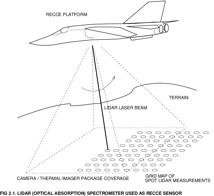
A suitable Laser Remote Sensing spectrometer with the capability to measure the atmospheric concentration of such telltale substances at a distance, could be used to provide a chemical trace "map" of an area of interest.3 A reconnaissance package on an aircraft so equipped [Fig.2.1] would sweep its Lidar over the terrain beneath the aircraft, taking a grid of point measurements. As the laser "spot" would be reflected off the surface of the earth, concentrations at ground level could be measured. Where an area of interest is not particularly well ventilated by wind, telltale chemical traces may be concentrated, further increasing the sensitivity of the method. Should the grid map be produced with a suitable density, postprocessing software could be used to produce other forms of presentation, such as false colour contour maps of equal concentration levels of chemicals of interest. These may then be overlayed over photographic or thermal images of the area of interest, to ease the photointerpreter's task. Hidden fuel storage depots would be a typical target of such reconnaissance. Because fuel tanks will typically vent hydrocarbon (fuel) vapour, so as to avoid the buildup of dangerous vapour pressures, any storage farm no matter how well hidden will produce a telltale vapour trace in the atmosphere above its location. Spillage is another good source of contamination. Similarly explosives or chemical warfare agent storage and loading facilities will also, unless particularly well filtered, identify their presence. Existing methods such as thermal imaging or ground penetrating Radar can both provide an indication of the presence of a buried facility. However, unless other means are used, it may be very difficult to establish beyond reasonable doubt what is the nature of the facility. The use of absorption spectroscopy could provide a means of narrowing down the options when assessing the output from other reconnaissance sensors. The detection of internal combustion engine exhaust gasses is another potential application for such technology. 4 The deployment and hiding of military vehicles in wooded areas has been a traditional means of concentrating resources out of the sight of the opponent's air power. An excellent example is the NVA effort along the Ho-Chi-Minh trail, during the SEA conflict, or Wehrmacht operations in the Ardenne during WW II. A concentration map of exhaust gas traces could be used as a means of determining whether the opponent has concentrated land warfare assets in a given area. This could in turn be used to cue subsequent reconnaissance with other sensors to confirm whether the observation was accurate or not. Where the presence of such forces is already known, impending activity such as preparations to move out of established positions may be detected once engines are cranked up and run in large numbers. This kind of early warning of movements is not provided by Radar, which requires the vehicles to be moving. It is worth noting that early warning of impending activity by monitoring Radar and communications emissions will not necessarily be available with a low technology opponent, or a very electronically disciplined opponent. Lidar would therefore close the gap in existing recce capabilities. A similar approach could be applied to detecting hidden heavy artillery emplacements. The propellants used by such weapons will leave a respectable trace of nitrogen oxides after firing. Providing that the Lidar scans over the emplacement before the propellant residue cloud has dispersed, it is reasonable to expect such a trace to be detected.5 Where the opponent is using self-propelled artillery, and moving position after firing, a combination of Nitrogen Oxide and exhaust gas monitoring scans will provide a trace to the current position of the SP artillery piece. Another potential area of use could be searching for dispersed mobile ballistic missile launchers. Older technology missiles such as the Scud are liquid fuelled, and where such missiles need to be fuelled before launch, it is likely that propellant spillage from hoses could provide a detectable chemical trace. Should such traces be detected in conjunction with automotive fuel and exhaust gas residues, it would be reasonable to assume that a ballistic missile is being prepared for launch.5 Should a missile have been launched, an aircraft despatched into the area of the launch should be able to track down the launcher using a suitable Lidar.
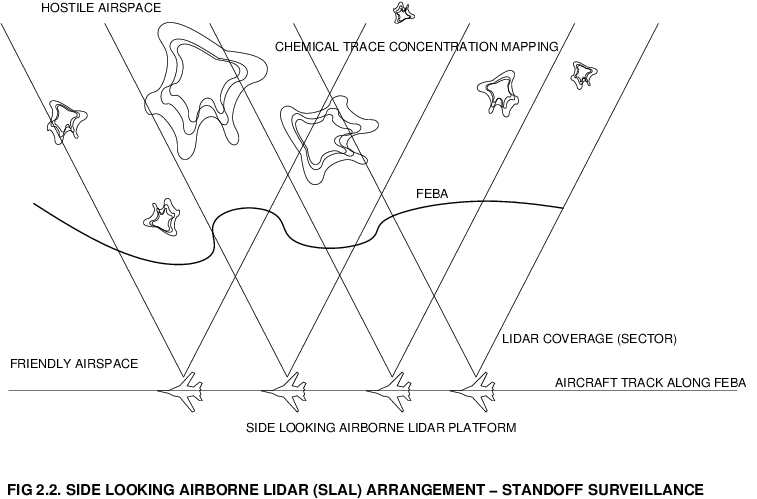
The reconnaissance Lidar scheme proposed above employs a down looking Lidar, as current technology has performance constraints which limit useful range to several nautical miles of distance.6 Should the range performance of such Lidars be significantly improved, for instance by a factor of 10 to 30, then other more elaborate mapping schemes may be used. An example would be a side looking arrangement, using a horizontal scan [Fig.2.2], where the aircraft would fly along the FEBA and look into hostile airspace from the sanctuary of sanitised airspace. This scheme would have the further advantage of allowing the use of more sophisticated mapping and imaging schemes [Fig.6,7]. This would allow the construction of a far more accurate picture of chemical traces in the area of interest. Colocating such equipment on a battlefield surveillance platform with a sidelooking Radar (SLAR) would then allow the fusion of Radar Moving Target Indicator (MTI) imagery, synthetic aperture (SAR) groundmapping Radar imagery and Lidar chemical trace concentration imagery. Fusion of data from multiple sensors would significantly improve confidence in target tracking and identification. An issue which may become important, in the context of the air land battle, is the proliferation of stealth technology. The US Army has expended much effort on the Comanche scout helicopter project, which has been designed with a very low frontal Radar cross section, and significantly reduced InfraRed signature, in comparison with types currently in service. Battlefield helicopters in this class may be very difficult to detect using conventional battlefield surveillance Radars (JSTARS, Orchidee, ASTOR) or AEW systems (E-3). Helicopters in NOE (Nap-Of-the-Earth) flight and hover are in a moderate to high engine power regime, and all the fuel burned ends up as a cloud of exhaust gas surrounding the position of the helo. This exhaust gas signature may not disperse well, particularly if the helicopter is masking itself in foliage, as one would expect it to. Should a battlefield surveillance Lidar be built with sufficient sensitivity and resolution to track armoured vehicles, it should also have the capability to defeat the stealthy battlefield helicopter. Further extending the paradigm, this approach may also be effective against fixed wing stealth aircraft, as a jet aircraft exhaust trail will contain concentrations of hydrocarbons of the order of parts per million, which can be 100 or more times the background atmospheric concentration.7 Should we see a proliferation of stealth technology in the next century, the ability to track such aircraft even under VFR conditions would significantly limit an opponent's opportunities to use his stealth aircraft productively. By constraining hostile stealth aircraft operations to IFR conditions where Lidar is ineffective, an opponent will be at the mercy of the weather and thus more predictable in terms of operational activity. The detection of chemical warfare agents has been proposed both in the BDA and reconnaissance situations. Its usefulness in a standoff battlefield surveillance platform as a means of early warning of chemical attack in progress is clearly beyond dispute. Other applications may also exist. One of perhaps anecdotal interest is the detection of troop concentrations by Lidar sensing of Ammonium (3 micron band) produced by the bacterial breakdown of urine, and Hydrogen Sulphide (4 micron band) produced by the decomposition of feces. The odor of an latrine could thus prove to be unhealthy in more than one way. A countermeasure reputed to have been used by the NVA against Ammonium sniffing sensor equipped aircraft in the SEA theatre involved the hanging of jars of urine off trees. A Lidar searching for more than one substance would be somewhat more difficult to deceive. For deception to be successful, multiple channels of deception must be used. The ability to search for a wide range of chemical traces, as well as thermal and visible optical images, creates a much wider range of information channels than can be dealt with by a conventional deception strategy. Should an opponent become aware of a chemical trace detection capability, that opponent will be faced with the difficulty of knowing what deception to use, and this uncertainty will increase the pressure which an opponent is subjected to. 5. The Limitations of Laser Remote Sensing in Reconnaissance and BDA ApplicationsWhile Laser Remote Sensing techniques offer the potential to unambiguously identify chemical substances in an area of interest, the method has limitations as all other sensors do. The first limitation is in the need to carry specialised equipment in addition to existing reconnaissance sensors or Bomb Damage Assessment cameras. This will add weight to the aircraft's sensor suite, as well as increasing the cost and maintenance requirements of the aircraft's systems. The second limitation lies in the attenuating properties of the atmosphere and obscurants such as dust, haze, water vapour or low cloud. These will attenuate the laser radiation reflected by the target , both by scattering and selective absorption. This will limit the range at which any given airborne spectroscopic sensor can accurately take a reading off a target, as well as impose weather constraints upon the usage of the method. Lidar will not penetrate cloud or thick haze and requires line of sight to the target. The greater the range and atmospheric losses, the larger the optics, the more powerful the laser and the more sensitive the detector required in the equipment. Ultimately this will place limits upon the useful range of such equipment of any given size and technology.8 The final noteworthy limitation of Laser Remote Sensing methods is their potential vulnerability, as with conventional photographic methods, to deception by a clever opponent. A HAS filled with 44 Gal drums of aviation fuel, expired missile rocket motors and spare tyres would be likely to register similar chemical signatures to a real aeroplane, should the HAS be successfully attacked and analysed by a Lidar. A similar tactic could be applied to creating bogus underground fuel tanks or vehicle concentrations. Whether the effort justifies the result is however open to debate, indeed the expending of significant resources by an opponent trying to defeat Laser Remote Sensing reconnaissance is a useful military effect within itself. Deception is however less likely to succeed should multiple reconnaissance or BDA sensors be used, and a combination of thermal imaging and Laser Remote Sensing techniques would provide substantially better resilience to deception than either method alone. The integration of Laser Remote Sensing techniques into the strike operations cycle is a simple task, no different from using any modern digital BDA or Recce camera system. Upon returning from a sortie, the cartridge tape containing the Lidar data would be loaded on a desktop computer. Postprocessing software would then produce contour map or false color overlays of chemical trace data which could be superimposed over imagery collected with conventional IR and optical cameras. Should suitable presentation be used, the additional overhead in fusing the Lidar data with other imagery should be minimal.
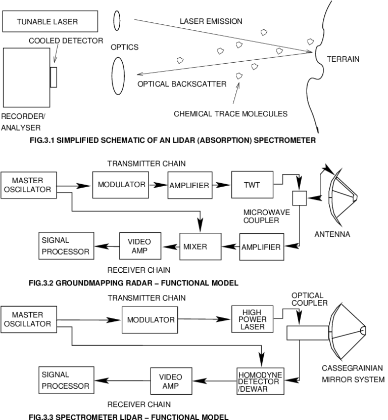
6. Design Strategies for Airborne Laser Remote Sensing LidarsDesigning and building Lidars for recce and BDA applications is not a trivial task, even if much of the technology used in such designs is derived from the established Electro-Optical sensor and Radar technology base. Indeed, the fundamental operating principle of Lidar differs little from Radar - a pulse of Laser light is emitted and backscatter from the atmosphere and background is analysed for absorption by chemical species of interest [Figure 3].
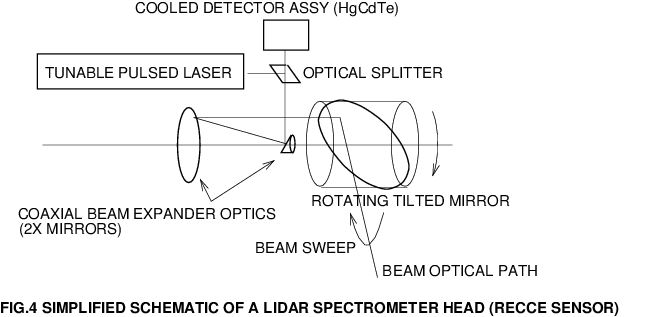
Functionally such Lidars would most closely resemble existing groundmapping Radars. There are however some fundamental differences. Whereas a Radar will use a Microwave or other antenna, a Lidar must employ a geometrically precise mirror arrangment, typically using a Cassegrainian dual reflector arrangement. Just as a Radar antenna must be stabilised in space and scan for targets, so must a Lidar mirror be stabilised and pointed to produce a scan pattern. Where a Radar employs a Travelling Wave Tube (TWT), or Magnetron, as a high power Microwave source, a Lidar will need to employ a high power, tunable, high Pulse Repetition Frequency (PRF) Laser. The difficulty in building such Lasers has been one of the fundamental technical obstacles which have restricted the growth in Lidar usage. Receiver design is another area where a Lidar has both similarities and differences to a Radar. The fundamental difference is that a Lidar will need to use a cooled optical detector, rather than a Microwave front end amplifier. Sensitivity performance dictates that a Lidar use either heterodyne or homodyne coherent detection techniques, which are conceptually no different from those used in Radar. However an optical coherent detector must mix the Lidar return, often up to 1,000,000,000 times fainter than the transmitted Laser pulses, with light from reference Master Oscillator Laser to produce a detectable signal. The wideband electrical video amplifier chain is used to boost the detected Lidar return to level where it can be fed into a signal processor, not surprisingly, is not very different from a Radar video amplifier chain. A signal processor for a Lidar would not differ significantly from a device built to process groundmapping Radar signals, although the software algorithms would need to be different given the idiosyncrasies of Lidar. A Lidar purpose built for recce applications such as depicted in Figure 2 will require a scanning mirror arrangement which will sweep the terrain beneath the aircraft, in a fashion not unlike an IR Linescan Recce camera. Beam stabilisation would be performed by a servo driven secondary mirror. A suitable arrangment of optical couplers and beam deflecting mirrors would separate the outgoing high power laser beam from the received return signal, as well as couple the reference Master Oscillator beam/signal into the detector. The detector would be a single Indium Antimonide (InSb) or Mercury Cadmium Telluride (HgCdTe) element, cooled either by Peltier thermoelectric or Joule-Thompson gas expansion refrigerator. The detector materials and refrigeration techniques are well established in existing heatseeking missile designs, such as the AIM-9 which has employed this technology for many years. The best accuracy in Lidar spectrometers has been achieved by the use of DIAL (DIfferential Absorption Lidar) techniques. A DIAL Lidar will transmit a pulse at the wavelength of interest, followed by a pulse at a slightly different wavelength which is, importantly, not absorbed by the chemical substance of interest. Subtracting the two returns from the two pulses yields the absorption due the chemical traces of interest. This elegant and simple method automatically compensates for atmospheric losses, terrain reflectivity and any other beam losses. The use of DIAL techniques dictates a precisely tunable pulsed Laser in the instrument. Because most chemicals of interest absorb in the mid InfraRed wavelength region, the Laser will need to cover a number of wavelengths between 2.5 and 6 microns. As noted, such lasers are difficult to build. The best technological option at this time is the use of a frequency tripled or doubled pulsed Carbon Dioxide gas laser, which can deliver the necessary power to provide a range of several miles. Frequency doubling and tripling employs Parametric Oscillator techniques, where an optically non-linear crystal excited by the 10 micron band Laser emits at one half or one third the wavelength of the exciting Laser. A number of tuning techniques exist, all of which are based upon the idea of suppressing the Laser's oscillation at wavelengths which are not of interest. A recce sensor which must sweep across a broad spectrum of wavelengths will need to produce a "chirped" train of pulses, each at a different wavelength. Arrangements which use a rotating multifaceted mirror and a diffraction grating will produce exactly this effect.
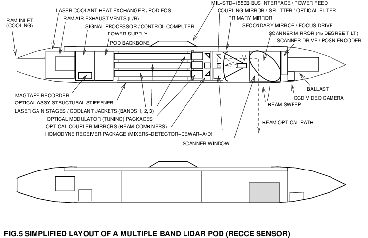
Assuming the use of the existing Lidar and Radar technology base, it is not difficult to envision a podded Lidar package suitable for centreline carriage on a recce aircraft such as an RF-16C or RF-4C [Figure 5]. In this instance, two or three mid InfraRed Lasers are packaged together with a shared detector element, cooling system, video chain and signal processor. Each Laser transmitter would use a tuned and pulsed low power Master Oscillator Laser which would then feed the frequency doubled or tripled Power Amplifier Laser stages, as well as providing a reference signal for the homodyne detector/mixer. The pod master computer would synchronise the operation of the Lasers and beam scanning optics, and the Signal Processing computer would then extract DIAL measurements from each pair of pulses which are sent and recieved. Precise calibration of timing and inherently narrow beams would provide for exact range measurements. Processed Lidar returns could be stored on magnetic cartridge tape, or datalinked to other platforms.
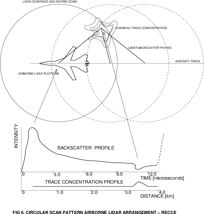
If the Lidar is built with sufficient sensitivity performance, then a circular scan technique similar to classical surface search Radar can be employed [Figure 6, 7]. This would allow the production of a Radar like PPI scan image of the terrain covered by the aircraft, which could be not only be recorded, but also displayed in the cockpit. This would allow searches for targets of opportunity, as well as allowing the aircraft to fly abeam of targets thus avoiding fire from AAA, small arms and MANPADS.
Should Laser Remote Sensing Lidar technology evolve to the level of compactness seen in contemporary FLIR and Radar, then the future possibility of a nose mounted Attack Lidar Set, analogous to an Attack Radar, should not be discounted. A bomber equipped with Imaging Synthetic Aperture and Moving Target Indicator (MTI) Radar, FLIR and chemical sensing Lidar would be particularly well equipped to hunt for targets of opportunity such as armour or mobile missile launchers. Fusion of four sensors should provide for automatic target identification with a high level of confidence. As with Radar, a broad range of alternatives exist for Lidar scan. Applications such as BDA or air-air search for exhaust plumes could for instance use Raster scanning techniques, analogous to TV, or derivatives of established conical scanning techniques. 7. ConclusionsSuitably implemented, Laser Remote Sensing methods could be profitably applied to reconnaissance and Bomb Damage Assessment. The use of this technology in conjunction with conventional sensors provides a means of determining chemical traces in the area of interest, which for many target types can provide the necessary information to confirm target type or damage level. This can then be used to resolve uncertainties in the output from conventional sensors and available intelligence, thereby increasing the level of confidence in targeting and damage assessment. In the post Cold War context, where economy of force is a critical factor, Laser Remote Sensing offers the potential for significantly more accurate strategic and tactical reconnaissance as well as Bomb Damage Assessment. This in turn will provide for substantially better utilisation of air assets, thereby creating a force multiplication effect within any air force deploying this capability. The potential payoff should not be underestimated. ž AcknowledgementsSpecial thanks to Dr Lew Whitbourn, Dr Roy Howard and the RAAF Air Power Studies Centre for their advice during the preparation of this paper. Any omissions are the author's responsibility. Footnotes1. Typical contemporary applications will use a laser which is tunable, and usually tuned to the specific wavelength of interest. Should several substances be searched for, then the laser is typically retuned to the appropriate wavelength for the measurement. This is usually achieved by using optical resonators or diffraction gratings, which selectively reinforce lasing at the desired wavelength. Conventional lasers using Fabry-Perot cavities will usually produce a range of wavelengths concurrently, and the addition of the selective tuning element in the optical path will suppress lasing at undesired wavelengths. In this fashion a spectral range can be covered, and given the capability of the laser, many spectral lines associated with a range of chemical species can then be collected. 2. Measures describes a number of mobile Lidar systems used for measuring the composition of power station smokestack emissions. The exhaust from such smokestacks is not only hot, but will also contain a substantial amount of particulate ash. In this respect, it is very reasonable to expect similar optical properties to the smoke and dust clouds vented from a shelter hit by a penetrating munition [pp408]. 3. Measures describes a number of experiments which are relevant to this discussion. What is of particular importance is that the CH3 group associated with straight chain hydrocarbons, contained in jet fuels and some automotive fuels, has a resonance in the 3.5 micron InfraRed band. This means that an instrument designed to detect this spectral line can in fact identify the presence of a range of hydrocarbons concurrently. Examples of hydrocarbon detection include experiments where ethylene concentrations of 10 ppb were detected from backscatter off foliage at 5 km distance, using a 15J/100 nsec pulsed Carbon Dioxide laser with 300 mm diameter receiver optics. Another experiment detailed in this reference involved the remote detection of methane concentrations of 2 to 4 ppm, using a 3.3 micron wavelength laser (pp391, 394). Automotive and jet fuels contain a number of volatile components, and a substantial fraction of aromatics. Jet fuels such as Jet-B (D-1655) or JP-4 (MIL-J-5624F) are typically a blend of gasoline and kerosene, with an aromatic content of about 20-25%, and an alkene content of about 5% [TREAGER79]. 4. ibid pp388. Internal combustion engine exhaust gasses contain a number of readily detectable trace substances. Nitric Oxide, Carbon Monoxide and Ethylene are notable instances, although a range of hydrocarbons may also be present. Experiments in monitoring Carbon Monoxide concentrations in an urban area detected the starting and stopping of an automobile engine, against a background concentration of about 400 ppb of Carbon Monoxide. The tests involved a Carbon Dioxide laser. Other experiments [pp389] detected Nitric Oxide concentrations of 300 to 400 ppb, against a background of about 100 ppb, with peaks associated with the presence of individual busses and trucks. Hydrocarbons may also be an attractive trace for such applications, Ethylene in particular as its natural background concentrations are very low [pp8, pp9]. 5. ibid. pp 392. A frequency doubled Carbon Dioxide Lidar emitting in the 5.3 micron band was used to detect Nitric Oxide concentrations of about 250 ppb at a range in excess of 1 km. Nitrous Oxide concentrations of about 290 ppb have been detected by a 3.9 micron band Lidar at ranges of several kilometres, while nitrogen Dioxide has been successfully measured by a 450 nanometre band frequency doubled dye laser Lidar at concentrations of about 25 ppb at an unspecified range [pp398]. 6. The Australian CSIRO research Lidar was designed to produce 10 micron band measurements of mineral reflectivity. The system is carried by a Fokker F27, on an internal pallet, and produces a 2 metre diameter laser spot from an altitude of about 1,500 ft. Of particular interest in this design is the Carbon Dioxide laser, which is tuned through about 100 separate wavelengths in the 9 to 11 micron range available from the Carbon Dioxide lasing medium. The laser produces a peak pulse power in the range of 50 to 100 Watts, and uses a folded cavity with a 3 metre optical length. While this system is customised for its application, it could be readily adapted to trialling the applications discussed in this paper by additional signal processing hardware to provide for a DIAL mode of operation. 7. ibid. pp391. A relevant experiment detailed the detection of 100 ppb of toxic rocket fuel over distances between 0.5 and 5 km, using the 5.3 micron Lidar detailed above. Rocket fuels such as Hydrazine, Unsymmetrical Dimethyl-Hydrazine and Monomethyl-Hydrazine all have resonances within the coverage of the 10.6 micron band Carbon Dioxide laser [pp394]. 8. Other effects which can influence accuracy in BDA situations are Doppler shifts in spectral components resulting from violent turbulence during explosions and combustion, as well as broadening of spectral lines due thermal motion of atoms or molecules in such environments. Both of these effects need to be accounted for in Lidar sensor design. ReferencesEisberg R.M., Resnick R., Quantum Physics, Wiley, 1974 Evers S., Aircraft System to Detect Chemicals from 100 km, AW&ST November 14, 1994 Kopp C., Air Warfare Applications of Laser Remote Sensing, RAAF APSC Working Paper 33, Royal Australian Air Force, Canberra, 1995 Measures, R.M, Laser Remote Sensing, Fundamentals and Applications, Wiley Interscience, New York, 1984 Ramo Simon, et al, Fields and Waves in Communications Electronics, Wiley, 1965 Skoog D.A., West D.M., Principles of Instrumental Analysis, 2nd Edition, Saunders College, Philadelphia, 1980 Whitbourn L.B. et al, An Airborne Multiline Carbon Dioxide Laser System for Remote Sensing of Minerals, Journal of Modern Optics, 1990, Vol.37, No.11, 1865-1872 Treager I.E., Aircraft Gas Turbine Engine Technology, 2nd Edition, McGraw-Hill, 1979 Williams D.H et al, Spectroscopic Methods In Organic Chemistry, 3rd Edition, McGraw-Hill (UK) Ltd, 1980 Biography
Disclaimer The conclusions and opinions expressed in this document are those of the author cultivated in the freedom of expression, academic environment of Air University. They do not reflect the official position of the US Government, Department of Defense, the United States Air Force or the Air University. [Air & Space Power Chronicles Home Page | Feedback? Email the Editor ] |
||
| APA Mirror - US Air Force Air & Space Power Journal - Chronicles | ||
|
|||||||||||||
|
|
|
|
|
|
|
|
||||||
|
|
|
|
|
|
|
|
||||||
|
|||||||||||||
| Artwork, graphic design, layout and text © 2004 - 2014 Carlo Kopp; Text © 2004 - 2014 Peter Goon; All rights reserved. Recommended browsers. Contact webmaster. Site navigation hints. Current hot topics. | |||||||||||||
|
Site Update
Status:
$Revision: 1.753 $
Site History: Notices
and
Updates / NLA Pandora Archive
|
|||||||||||||
|
|
Tweet | Follow @APA_Updates | |||||||||||
|
|
|||||||||||||
|
|
|||||||||||||