|
APA Notice
This
article predates the mid December, 2006, announcement
by Defence that
Super Hornets may be sought as gap fillers for the RAAF, and subsequent
decision to acquire these aircraft. The article
does not constitute an endorsement of
that proposal in any fashion and should not be interpreted
to be such by any parties. It concentrates primarily on the
history and flying qualities of the aircraft. Any attempt to
present this article as an endorsement of the Super Hornet
decision will
be considered to be intentional and mischievous
misrepresentation.
|
|
1 Part 1 History and Analysis
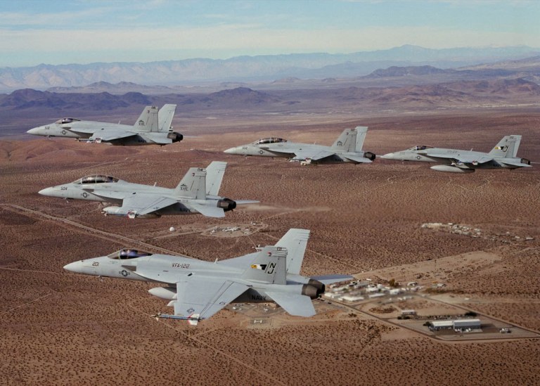
The F/A-18E/F Super Hornet will become over the next decade the
mainstay
of the US Navy's carrier-borne fighter fleet. As one of the very
fewfighter
aircraft to remain in production around the end of the decade, it is
also
very likely to be carefully scrutinised as a potential replacement for
the RAAF's F/A-18A/B Hornet fleet.
Therefore this aircraft is of considerable interest to the
Australian
observer. In this two part feature the author will explore the
F/A-18E/F
in some detail, including a demonstration flight performed during the
2001
Avalon airshow.
The best starting point for any discussion of the F/A-18E/F is
the historical
background of this aircraft.
1.1 Evolution of the Hornet
The genesis of the F/A-18 family of fighters is the period of the early
seventies. At this time USN Carrier Air Wings were equipped with a mix
of the MDC F-4 Phantom, the Grumman A-6E Intruder, the LTV A-7B/E
Corsair,
with the then new F-14A beginning to enter service. The F-14A, born
from
the late 1960s VFX/VFAX studies, was to replace initially the F-4
Phantom
family, while plugging the gap in fleet air defence capability
resulting
from the collapse of the Phoenix equipped F-111B program.
US Navy planning at that time envisaged a future force
structure centred
upon the F-14 family. The TF30 equipped F-14A was to be a transitional
model, soon to be replaced in production by the more agile F-14B,
equipped
with the F401 engine, a derivative of the F100-PW-100 used in the
F-15A.
A follow-on multirole variant of the F-14B, designated the F-14C, was
to
replace the A-6E and the bombing capability of the F-4 series. This was
a force structure designed to project force up to 600 NMI from the
carrier
battle group, in heavily defended airspace.
In the funding collapse following the Vietnam conflict, the
F-14B and
F-14C died. This was in part due to a large cost growth in the F-14A,
which
almost bankrupted Grumman, but also in part to a massive reduction in
available
funding during this period. Only the F-14A remained in production, to
be
supplanted by the F110 powered F-14B and F-14D models during the final
years of production.
The A-6E soldiered on, intended to be upgraded during the
early nineties
to the A-6G configuration, and eventually replaced by the A-12A Avenger
II (Dorito) stealth bomber. With the collapse of the Evil Empire, the
A-6G
and A-12A both died in the following budgetary upheavals, with the A-6E
leaving service during the 1990s.
The F-14 was a superb replacement for the F-4 in the fleet air
defence
role, but its high cost and resulting reductions in numbers meant that
no replacement would available for the multirole F-4 series, which
performed
a significant portion of the fleet's strike operations. The USN was
thus
confronted with the problem of how to provide a fighter bomber cheaper
than the F-14 series, to replace the F-4 and the increasingly less
survivable
A-4 Skyhawk and A-7 Corsair bomb trucks.
A range of studies were performed to define a fighter to
fulfill this
role, as a second generation VFAX program. These included analyses of
a navalised F-15 strike fighter, which were rejected due to the air
force
centred design optimisations of the basic aircraft - the wing design of
an F-15 is not well adapted to carrier recoveries. The reality of the
role
to be performed was, however, was that the fighter would end up
inevitably
in the size and weight class of the F-4 or F-15. The dictates of
Breguet's
equation in payload radius impose a given airframe size.
At this time the USAF was experimenting with the idea of
lightweight
fighters to supplement the relatively expensive F-15A air superiority
fighter,
and very expensive F-111D/F strike fighter. The LightWeight Fighter
(LWF)
program yielded the Northrop YF-17A and the GD YF-16A. The General
Dynamics
fighter became the Lawn Dart/Viper/Falcon, or production F-16A-D
multirole
fighter.
The Office of the Secretary of Defence (OSD), frustrated at
perceived
USN intransigence over the F-14 program, subsequently directed the Navy
to pursue a similar program, with the aim of replacing the F-4, A-4 and
A-7 with a similar lightweight fighter to the F-16. Given the USN's
long
standing aim of a force structure capable of power projection to a 600
NMI radius, this was not a popular directive. However, might is right,
and the USN eventually proceeded with a lightweight fighter, based upon
the YF-17 demonstrator. The new F/A-18A was based upon the aerodynamic
design of the YF-17, but enlarged as much as the DoD bureaucracy would
permit - to an empty weight of 21,000 lb, or about 2/3 that of the
F-15A.
The F/A-18A was optimised from the outset as a dual role
fighter, with
BVR missile capability, superb manoeuvrability for the period, and a
fully
digital weapon system and glass cockpit which allowed reconfiguration
between
air-air and air-ground software modes at the touch of a pushbutton.
Reliability
and low support costs were deemed a priority, and the engines and
electronics
were significantly derated against contemporary designs to achieve an
unprecedented
mean Time Between Failure for the period. Top end performance was
sacrificed
to achieve cost and reliability optimisation.
The production F/A-18A entered service in VMFA/VFA or
fighter-attack
squadrons, progressively replacing fleet A-4, A-7 and F-4 squadrons
with
a single type. When introduced, it offered close in combat capability
which
was difficult to contest by most of its contemporaries, as the hybrid
wing
design and digital fly by wire controls provided exceptional high AoA
manoeuvre
and low speed turning performance. The aircraft's principal limitation
was in its combat radius - the combination of leaky turbojet engines,
pylon drag and 11,000 lb of internal fuel resulted in an effective
unrefuelled
radius between 250-400 NMI, depending on load, profile, combat fuel
reserves
and external tank configuration.
The F/A-18A/B was exported to Australia, Canada and Spain. It
was supplanted
in production by the F/A-18C/D, which had slightly uprated engines to
offset
weight growth, and a range of various avionic and detail modifications.
This aircraft was exported to Switzerland, Kuwait, Malaysia and
Finland.
As an export product, the F/A-18 faced a lightweight fighter market
saturated
with cheaper and non-BVR capable F-16As, and a heavyweight fighter
market
saturated with F-15A-D (Israel, Saudi Arabia and Japan). As a result,
it
never achieved the hoped for volume of export sales.
Operationally the F/A-18A-D series has proved to be a popular
aircraft,
with excellent operational reliability, handling and flexible weapons
capabilities.
Its principal limitation was in combat radius performance, which proved
to be a major issue with the progressive retirement of the A-6 fleet,
which
provided the USN's primary KA-6D tanker aircraft. As the larger KA-3D
tankers
had already been retired, tanking capacity was becoming an ever scarcer
commodity by the nineties.
The nineties also resulted in ongoing budgetary and force
structure
cuts, as the post Cold War drawdown continued. As noted earlier, the
A-12A
and A-6 upgrades died, and the F-14D production was terminated. The
USN's
primary role of Cold War blue water maritime control, aimed at
defeating
the USSR's massive SSN and Backfire strike forces, was supplanted by
littoral
warfare, in effect modern gunboat diplomacy intended to provide a
rapid
reaction capability to deal with problem nations disturbing the peace.
USN carriers played key roles in the 1991 Desert Storm campaign, the
1990's
Balkans campaigns, the ongoing war of attrition against Saddam
Hussein's
regime, and the late nineties standoff between Taiwan and the PRC,
during
which the PRC threatened Taiwan with ballistic missiles.
This is an environment in which top end air superiority and
deep penetration
strike capabilities are considered ancillary to the capability to
flexibly
strike against well defended coastal targets, suppress integrated air
defences
and provide air support and top cover for amphibious forces. Indeed,
with
the retirement of the A-6E, the remaining F-14 force has been
progressively
adapted to deliver guided and unguided bombs, earning the new informal
label of Bombcat.
By the early nineties it was clear that the aging F-14 fleet
would have
to be replaced over the coming decade or so, and a replacement
concurrently
provided to plug the gap left by the never replaced A-6E fleet. The
core
requirements for such a replacement aircraft were a combat radius
competitive
against the 600 NMI class F-14/A-6 combination, and CAP endurance in
fleet
defence operations competitive against the F-14 series.
During the early nineties considerable effort was expended in
studies
aimed at adapting the new USAF F-22A to carrier operations, as the
F-22N.
Problems soon arose, as the baseline land-based F-22 is not optimised
for
the unique carrier environment. The most difficult issue proved to be
the
wing - the unhappy experience of the USN with blown flaps on the F-4
series,
the obvious solution to achieving the required recovery speeds for
trapping
such a large aircraft, led to the adoption of a swing wing
configuration.
This in turn pushed up the cost of the redesign, since the stealth
characteristics
(ie shaping) would have to be completely requalified, adding already to
the considerable costs of a structural redesign and avionic system
redesign.
In effect the F-22N would be a new aircraft, resulting in little saving
through commonality. Given the required number of aircraft, this proved
to be unaffordable to a USN already under major budgetary
pressures.
What the USN needed was a aircraft which could eventually
replace the
aging F-14 and F/A-18A-D fleet, plug the hole left by the A-6E and
KA-6D,
and do so within a restricted development budget and timeline.
The result of these pressures is the F/A-18E/F Super
Hornet.
1.2 The F/A-18E/F Super Hornet
The Super Hornet is substantially a new aircraft, which shares
only
limited structural commonality with the F/A-18A-D family of fighters.
While
the F/A-18E/F forward fuselage is derived from the F/A-18C design, the
wing, centre and aft fuselage, tail surfaces and powerplants are
entirely
new. The baseline avionic system is however largely derived from the
F/A-18C,
with planned growth through further evolved derivatives of the radar,
EW
and core avionic systems, and entirely new systems where
appropriate.
The designation F/A-18E/F reflects the fact that the aircraft
is derived
from the F/A-18A-D, even if it is a significantly larger airframe
design
- the program was implemented as an Engineering Change Proposal (ECP)
to
avoid a costly demonstration program and fly-off, as has occurred with
the F-22/YF-23 and JSF. A side effect of this idiosyncrasy in
nomenclature
is that the F/A-18E/F is frequently dismissed as just another Hornet,
yet the aircraft is different in many respects.
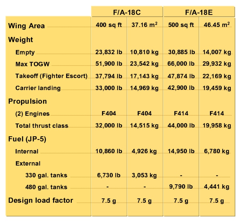
From a design perspective, the most notable change in the
Super Hornet
is its size, designed around an internal fuel (JP5) capacity of 14,700
lb, or 36% more than the F/A-18C/E. This most closely compares to the
F-15C,
which has around 10% less internal fuel than the Super Hornet.
Sizing around a 36% greater internal fuel load, with the aim
of retaining
the established agility performance of the F/A-18C, resulted in a
larger
wing of 500 sqft area, against the 400 sqft area of the F/A-18C, a 20%
increase. The consequent sizing changes result in a 30,885 lb empty
weight
(31,500 lb basic weight) aircraft, a 30% increase against the F/A-18C.
Not surprisingly, the aircraft's empty weight is 8% greater than the
F-15C,
reflecting the structural realities of catapult launches and tailhook
recoveries.
The larger F414 engine, a refanned and evolved F404 variant,
delivers
20,700 lb static SL thrust in afterburner, which is around 8% less than
the F100-PW-220 in the F-15C.
The simplest metric of the F/A-18E/F is that it is an F-15A-D
sized
F/A-18C derivative, optimised for the naval environment. The similarity
in size between the F/A-18E/F and F-15A-D is no coincidence - as the
original
VFAX studies in the 1960s and 1970s showed, this is the optimal fighter
size for the given combat radius. In effect, the F/A-18E/F is what the
F/A-18A Hornet should have been from the outset, had it not been
hobbled
at birth by a budget driven bureaucracy.
Size is where the similarity between the Super Hornet and
Eagle end,
since the Super Hornet is optimised aerodynamically around the
F/A-18A-D
configuration, with a focus on transonic manoeuvre and load carrying
performance,
and carrier recovery characteristics. In terms of raw performance, the
Super Hornet is very similar to the F/A-18C, but provides significantly
better CAP endurance and operating radius by virtue of its larger wing
and internal fuel load.
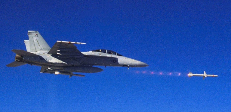
With three 480 USG drop tanks, full internal fuel, combat and
reserve
fuel allowances, 8 x AIM-120 AMRAAMs and 2 x AIM-9 Sidewinders, the
aircraft
has a point intercept radius in excess of 650 NMI, with some
assumptions
made about expended missiles. This is radius performance in the class
of
the F-15C.
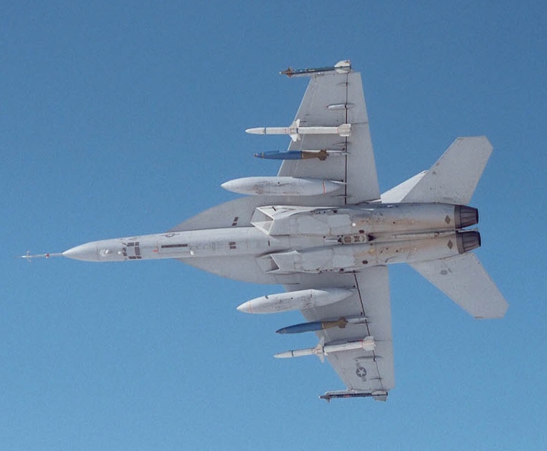
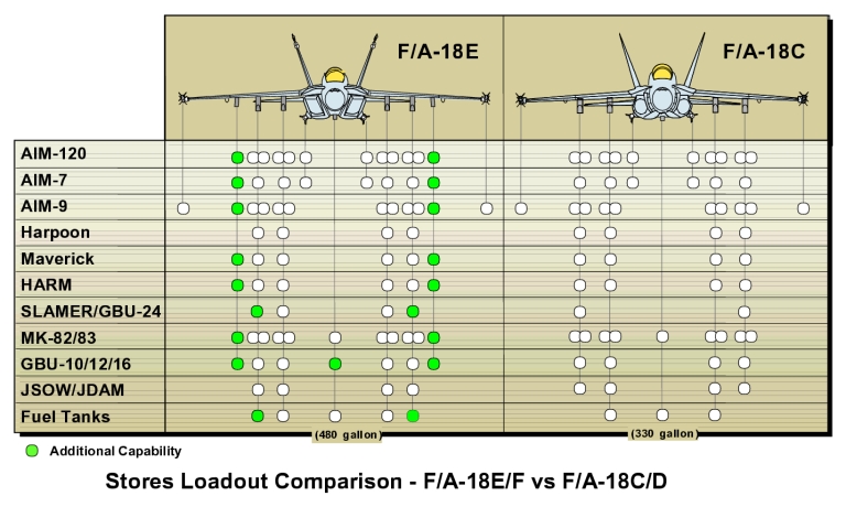
Like the F/A-18A-D, the F/A-18E/F was designed from the outset
for a
dual role fighter bomber mission environment. The enlarged wings have
three
hardpoints each, typically loaded with a pair of 480 USG tanks inboard
and weapons on the pair of outboard stations. The wingtip Sidewinder
rail
is retained.
A notable aerodynamic feature is a significantly enlarged
strake design
over the baseline Hornet, intended to improve vortex lifting
characteristics
in high AoA manoeuvre, and reduce the static stability margin to
enhance
pitching characteristics - Boeing cite pitch rates in excess of 40
degrees
per second.
Structurally the Super Hornet is built largely from aluminium
alloys,
with extensive use of carbon fibre composite skins in the wings, and
titanium
in several critical areas. The design load factor limit of 7.5G is
identical
to the F/A-18A-D.
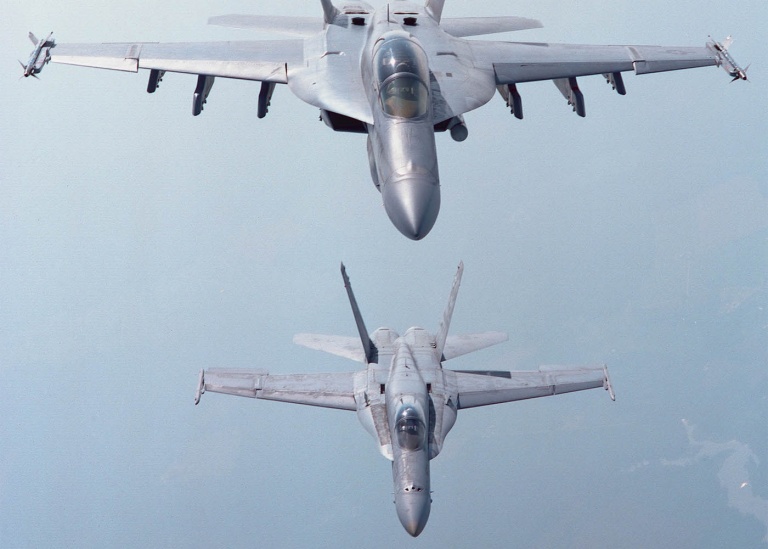
The most notable visual difference between the F/A-18A-D and
F/A-18E/F,
to the casual observer, are the engine inlets. These are are fixed in
geometry,
but using a rectangular geometry more akin to the F-15 design.
The inlets represent a key design optimisation intended to
reduce the
aircraft's forward sector radar cross section. The edge alignment of
the
inlet leading edges is designed to scatter radiation to the sides, and
fixed fanlike reflecting structure in the inlet tunnel performs a
role
analogous to the mesh on the inlets of the F-117A, keeping microwave
illumination
off the rotating fan blades.
The F/A-18E aircraft makes considerable use of panel join
serration
and edge alignment. Close inspection of the aircraft shows considerable
attention paid to the removal or filling of unnecessary surface join
gaps
and resonant cavities. Where the F/A-18A-D used grilles to cover
various
accessory exhaust and inlet ducts, the F/A-18E/F uses centimetric band
opaque perforated panels. Careful attention has been paid to the
alignment
of many panel boundaries and edges, to scatter travelling waves away
from
the aircraft boresight.
It would be fair to say that the F/A-18E/F employs the most
extensive
radar cross section reduction measures of any contemporary fighter,
other
than the very low observable F-22 and planned JSF. While the F/A-18E/F
is not a true stealth fighter like the F-22, it will have a forward
sector
RCS arguably an order of magnitude smaller than seventies designed
fighters.
Since every deciBel of RCS reduction counts until you get into the
range
of weapon payload RCS, the F/A-18E/F represents the reasonable limit of
what is worth doing on a fighter carrying external stores. None of the
RCS reduction features employed in the F/A-18E/F are visible on any of
the three Eurocanards, which raises interesting questions about the
relative
forward sector RCS reduction performance of these types.
The Super Hornet employs a further evolved derivative of the
F/A-18C
avionic package. While the AN/APG-73 radar, common to the RAAF HUG, is
retained, provisions will be made in production blocks for the
AN/APG-79
(formerly AN/APG-73 RUG III phased array) Active Electronically Steered
Array (AESA) retrofit. The new ATFLIR targeting pod will also be used,
employing a new midwave 4-5 micron band Focal Plane Array high
resolution
imager.
The
new
ATFLIR is a high resolution midwave design, which is a
generation in technology beyond most of the FLIR targeting pods
currently
in operational use. This targeting pod will supplant the existing
F/A-18C
pod set (Photo Boeing).
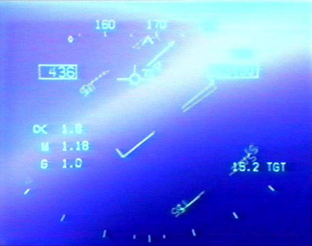
The APG-73 provides very respectable air-ground modes,
including
synthetic aperture modes (depicted). With the capability to interleave
MTI modes with surface mapping modes, the radar provides a potent
capability
against battlefield and maritime targets . The APG-79 active
phased array radar
(formerly APG-73 RUG III) is
a planned growth feature for the F/A-18E/F family of fighters. It is
derived
from the baseline APG-73 by the replacement of the planar array antenna
with a solid state Active Electronically Steered Antenna array. This
will
provide the radar with the ability to timeshare operating modes
concurrently,
as well as improving jam resistance and reducing detectibility through
much reduced sidelobes .
The core avionic computing package is based upon militarised
COTS VMEbus
PowerPC processors (common to desktop Apple PowerMacs and recently
built
F-15Es), which are of the order of a hundred times more powerful than
the
16-bit generation AN/AYK-14 processors in the F/A-18C. This is a
significant
advancement in long term supportability, and provides a very robust
platform
for evolution of the onboard software OFPs. The cockpit software is
highly
integrated by the standards of Mil-Std-1553B bussed architectures, and
provides facilities for display fusion of MIDS datalink, RWR threat
information
and digital moving map displays.
While the preproduction aircraft employ a mix of cockpit CRT
and AMLCD
displays, the intent is to employ high resolution NVG compatible AMLCD
panels in production block aircraft. A strike optimised missionised
aft
cockpit with a large 10 x 8 inch AMLCD display is in development. The
JHMCS
Helmet Mounted Display will be employed to cue the new thrust vectoring
AIM-9X missile, with growth to cue air to surface weapons.
The EWSP package is build around a late model ALR-67 warning
receiver,
the now revived ALQ-165 ASPJ defensive jammer, supplemented by the
ALE-50
towed decoy and ALE-47 dispenser. Current growth plans include the
ALQ-214
RF countermeasures package and ALE-55 fibre optic towed decoy from the
IDECM suite. The latter is particularly effective against newer
monopulse
threat systems, since it can provide for long baseline crosseye
jamming.
The current configuration of the F/A-18E/F avionic package is
the most
advanced of any production aircraft based upon a Mil-Std-1553B bussed
federated
architecture, and is surpassed only by the much newer F-22A and JSF
architectures.
It is very likely that growth variants of the F/A-18E/F will see the
progressive
incorporation of avionics technology used in the JSF.
In terms of broad comparisons, the F/A-18E/F most closely
compares to
the late model F-15 variants. While it does not have the supersonic
optimised
wing and top end BVR combat and supersonic agility performance of
APG-63(V)2
phased array fitted F-15C models, it has a more recent avionic package,
radar cross section reduction measures absent on the F-15 and a very
modern
defensive EW package. In most key respects, the Super Hornet is a
substantial
improvement over the established F/A-18A-D models, especially in combat
radius performance. While the aircraft is frequently criticised for not
offering a dazzling supersonic agility and thrust/weight performance
increase
over the baseline F/A-18C, this was not a primary design objective.
Rather,
the aim was to provide a low risk near term growth aircraft exploiting
the established technology investment in the F/A-18C, and utilising
newer
technologies such as RCS reduction, integrated MIDS datalink and
advanced
countermeasures to improve the aircraft's survivability and lethality
without
the cost penalties of a clean sheet new design.
At this time Boeing and the USN have planned growth paths for
the basic
aircraft in avionics and weapons, and a new engine derived from the
F-22/JSF
technology base is seen to be an attractive addition, but as yet is
unfunded.
Considerable development has also been committed to an electronic
combat
derivative of the F/A-18F, colloquially termed the F/A-18G. This
aircraft
would replace the EA-6B Prowler, which is often considered too slow to
keep up with strike packages, with a fully combat capable escort jammer
and HARM shooter. The Airborne Electronic Attack Variant F/A-18F
derivative
would employ wing tip pods with receiver equipment, a mission avionics
package in the M-61 gun bay, and a mixed payload of AN/ALQ-99
derivative
high power support jamming pods and AGM-88 HARM or derivative
anti-radiation
missiles. This aircraft would in concept most closely resemble a fusion
of the F-4G Weasel and EF-111A/EA-6B models into a single type, which
would
retain most of the multirole capabilities of the basic F/A-18F
aircraft.
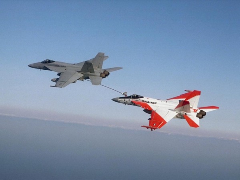
The use of a buddy refuelling pod in conjunction with four 480
USG wing
tanks is envisaged as a standard role for the F/A-18E/F, to provide a
tactical
tanking lost with the KA-6D. As the last KS-3 Viking tankers will soon
be out of life, the F/A-18E/F is likely to become the sole tanker asset
available to carrier airwings. Unlike the KA-6D and KS-3, it is not
going
to be an easy kill for an opposing fighter force, and since it is
substantially
faster it will be much more effective in reactive or emergency
refuelling
situations.
In terms of meeting the USN's aim for a low risk F-14/A-6 and
F/A-18A-D
replacement, in a timescale and budget compatible with current
circumstances,
and prior to the production of the high risk high payoff full stealth
JSF,
the F/A-18E/F clearly meets this objective.
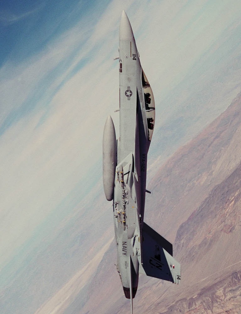
Supersonic
over
the
Bass Strait
2 Part 2 A Cockpit Perspective
One of the privileges of being a defence analyst and writer is the
occasional opportunity to indulge in flying some very interesting
aircraft.
This Avalon airshow Boeing very graciously invited me to partake in the
pleasures of flying the F/A-18F Super Hornet, equipped with the latest
revision of the digital flight control system. The aircraft far
exceeded
my expectations in both handling qualities and ease of cockpit
use.
The aircraft flown, BuNo 165797, was one of a pair of
production aircraft
brought out to the Avalon airshow, and operated by the US Navy at NAS
Lemoore
for weapons delivery trials. In terms of configuration these aircraft
were
equipped with a unclassified software load, designated 18EI "V".
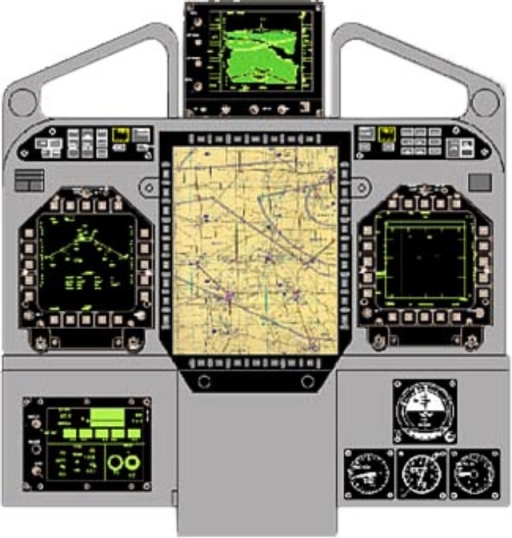
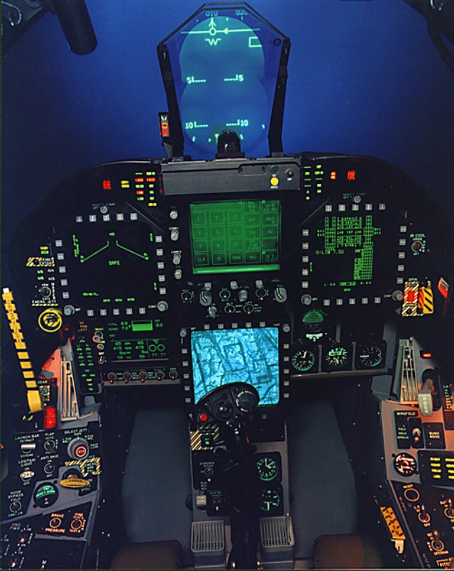
The cockpit configuration of these aircraft represents early
production
status, using cathode ray tube MultiFunction Displays (MFD, formerly
Digital
Display Indicators or DDI) for the left and right cockpit displays and
touch sensitive Up Front Control (UFC) panel, but full colour AMLCD
panels
for the centre moving map display. The aft cockpit had the centre MFD
installed
above the UFC panel.
Production configuration aircraft will have the aft cockpit
UFC installed
above the centre colour MFD, with growth variants using a much larger 8
x 10 inch AMLCD display for tactical situation data and moving maps.
The
aft cockpit does not have provisions for displaying HUD camera video on
the UFC or MFDs. Modes for the MFDs are all selectable by pushbuttons
on
the bezels. Production aircraft will use high resolution colour AMLCD
panels
in all displays, including the UFC.
The cockpit layout follows the basic style of late model
F/A-18C aircraft,
with an improved engine and fuel status display. Pilot feedback saw
Boeing
restore a rotary switch for the bingo fuel setting on this
panel.
The controls are standard stick and throttles, with mechanical
linkages
between cockpits for all but the rudder pedals. Mode controls for the
weapon
system are all incorporated in the HOTAS (Hands On Throttle And Stick)
controls, in addition to a master mode selector switch for A/A or A/G
in
the upper right of the cockpit. A single switch is also available to
disable
all aircraft electronic emissions from a single point, under EMCON
conditions.
Like other modern Boeing cockpits, the system is very easy to
operate
with well laid out mode select controls, and the capability to display
any format on any particular display. We flew the aircraft with the
left
MFD configured as a HUD symbology repeater, the centre MFD as a moving
map with overlayed navigation symbology and compass rosette, and the
right
MFD as the radar display.
2.1 Flying the Super Hornet
My demonstration pilot was Dave Desmond, Boeing's Chief Experimental
Test Pilot on the F/A-18E/F program and a former US Marine Corps
F/A-18A-D
operational pilot, who has flown every USN/USMC Hornet model since
1981.
During the Super Hornet flight test program he performed much of the
high
G handling tests for the aircraft with various load configurations. The
dazzling Avalon flight demonstrations were flown by Boeing Senior
Experimental
Test Pilot Mike Bryan, a former USN operational pilot.
Preparation for the flight was meticulous, with 1.5 hours
earlier in
the week dedicated to G-suit and helmet fitting, and a 2 hour preflight
briefing which included detailed discussion of emergency handling and
aircraft
recovery procedures should an ill behaved avian find its way through
the
windshield.
Two areas were available for demonstration flying, an
overwater corridor
south of Avalon and east of King Island for supersonic runs, and a
Hornet
Box east of Colac for overland flight demonstrations. Both were loaded
into the computer and displayed on the moving map, a very convenient
feature
once airborne. Weather conditions were cool, but clear with very little
cloud cover, ideal for a VFR sortie. The aircraft configuration was
very
light, with full internal fuel and all stations empty.
The plan for the sortie was to demonstrate some of the
aircraft's handling
characteristics and avionics, with the caveat that my very few hours of
recent aerobatic time would set bounds on how much we could explore the
envelope. Needless to say, 2 second increments of 5.5 G on a 200 HP
Z.242L
piston aerobatic trainer set limits on how much manoeuvre tolerance you
can gain in a hurry!
After the customary preflight walkaround I was strapped in and
hooked
up, upon which Dave briefed me on the use of the MFDs and UFC. Once
Dave
strapped in, the APU was started and then the engines. Oxygen is
generated
by the OBOGS which requires an operating engine. The pretakeoff BIT was
initiated on the MFD and the computer waggled all of the control
surfaces
- we dispensed with the habitual freedom of controls movement test. All
bit status information is tabulated on the MFD and all failed BIT tests
flagged as degraded on the MFD.
With engines turning, cockpit closed and seats armed, we
taxied to the
holding point and waited our turn in the queue for runway access.
For takeoff, Dave selected full afterburner and rotated at 105
KIAS.
Once airborne, we levelled off and accelerated to 370 KIAS for a 45
degree
pull up and full power climbout at 250 KIAS. The RoC off the runway was
around 27,000 FPM and we climbed to FL200 ft in about 1.5 minutes from
brake release. We reached FL260 at 297 KIAS and Dave handed the
aircraft
over to me with the customary stick waggle, pulling the throttles out
of
afterburner.
My first manoeuvre was a 360 degree left aileron roll at about
1/2 stick
input. The aircraft's response was very crisp and full roll rate
achieved
very quickly, at about 120 degrees/sec. The roll recovery was a little
messy, by force of habit I applied opposite stick to arrest the roll
rate
sharply and ended up 15 degrees into a right roll before I neutralised
the stick position. The Flight Control System (FCS) reacts very sharply
to control inputs and is perfectly damped from a pilot's perspective,
the
aircraft reacts almost instantaneously with G and roll rates
proportional
to stick deflection, at all airspeeds. Typically one inch of stick
deflection
produces 2 G of load factor, with very light and comfortable stick
force
for small control inputs. The Super Hornet can be flown very precisely
with gentle control handling, and is very easy to point.
While I maintained heading and altitude at Mach 0.95, Dave lit
up the
APG-73 and demonstrated the interleaved surface search mode. In this
mode
the radar interleaves synthetic Maritime Moving Target Indicator (MMTI)
tracks with raw video, the latter allowing the pilot to gauge the size
of the surface track. We locked up a pair of large transport vessels
tracking
the coastline on opposite headings. The size differences were clearly
evident
in surface search mode.
Rolling
through
360,
supersonic.
Once we completed the radar demo, Dave suggested I do a
supersonic run
and explore supersonic handling. I pushed the throttles past the
detente
into full afterburner and the aircraft accelerated through the sound
barrier,
with only a gentle bump to indicate that we had gone supersonic, the
FCS
smoothing out the Mach dither very effectively. Ten minutes into the
sortie, at 735 KTAS/485 IAS/M1.18 I initiated a half stick 360 left
aileron
roll, and recovered the roll cleanly. The handling was
indistinguishable
from the subsonic roll, with a roll rate of about 120 degrees/sec for a
half stick input. At Dave's suggestion, I pulled the throttle back out
of burner and initiated a climbing supersonic 2.0G heading change to
point
at 330 degrees to the Hornet Box over Colac. The aircraft turns very
smoothly
and little stick force is required to hold 2G, virtually no lateral
stick
input adjustments were required to keep the nose on the horizon.
Airspeed
bled off fairly slowly despite the applied G and altitude change.
While I maintained heading at 280 KIAS/FL350 kft, Dave
selected the
Ground Moving Target Indicator (GMTI) mode on the APG-73 and we started
hunting for some road traffic along the coastline at about 40-50 NMI
slant
range. Within seconds a row of tracks appeared across the scope, as
expected
outlining the Princes Highway near Colac. Some tracks intermittently
appeared
and disappeared, as trees blocked the line of sight between the radar
and
moving vehicles. Dave attempted a single target track on at least two
targets
but the foliage produced repeated dropouts - as much as we tried we
couldn't
cheat the physics of radar absorption.
We crossed the coastline, feet dry, to enter the Hornet
box.
2.2 The Virtual Speedbrake
The next handling demonstration involved involved the
speedbrake
and some high alpha low speed handling, an area in which many fighters
experience problems in maintaining direction and avoiding a departure
into
uncontrolled flight.
The first demonstration involved the virtual speedbrake
effectiveness
and handling in this configuration. The F/A-18A-D, like the F-15
series,
employs an upper fuselage hydraulically deployed speedbrake. The Super
Hornet has no such device, yet achieves the same effect through what
can
only be described as digital magic. The speedbrake function is
produced
by a balanced deployment of opposing flight control surfaces,
generating
drag without loss of flight control authority or change in aircraft
pitch
attitude.
Dave demonstrated the speedbrake function, and I was asked to
observe
over the shoulder and in the mirrors the raised ailerons, lowered
trailing
flaps, raised spoilers and splayed out rudders. Deceleration is smooth
and there is no observable pitch change.
At Mach 0.63 Dave invited me to fly another 360 aileron roll,
to observe
that the aircraft retains considerable control authority despite the
fact
that the rudders are splayed out, and the ailerons, spoilers and flaps
are generating balanced opposing pitching moments. I applied roughly
1/2
stick input and the aircraft very cleanly rolled through 360 degrees at
about 90 degrees/sec roll rate. I commented on the lower roll rate and
Dave observed that we were significantly slower, he then proceeded to
demonstrate
the roll again with a full stick input, producing around 180
degrees/sec
with a slight overshoot on recovery. The aircraft feels very stable
throughout
the manoeuvre and there is no observable change in control forces or
control
input response by the FCS.
2.3 High Alpha Handling
We then proceeded with some high alpha handling. Entry into
this
regime involved pulling back the power, while I tracked the control
movements
hands on, Dave progressively increased the amount of aft stick to
maintain
a constant airspeed around 90 KIAS. Power is concurrently added to
maintain
altitude and airspeed, and the aircraft was stable at 43 degrees alpha.
Dave then demonstrated a full 360 degree aileron roll while maintaining
over 40 alpha and close to full aft stick. Having worked through
several
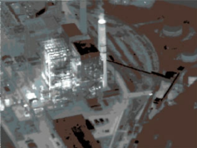
manoeuvres, we took at break to explore further radar modes. Dave
selected
the high resolution spot SAR mode and slewed the patch map over Colac.
After several sweeps the image sharpened up and we could resolve
individual
buildings and streets in the town, clearly contrasted against Lake
Colac.
The difference in groundmap quality against the sixties technology
real-beam
mapping APQ-161 truly reflects the 4 decades of intervening
technological
evolution. Having explored main street Colac for several minutes, we
turned
our attention to the Avalon airfield.
At about Mach 0.6 at FL200 Dave selected SAR spot mapping and
slewed
the radar over the Avalon parking area. With the nose pointing to
Avalon,
a few miles east of Colac, we had very little lateral Doppler and at
Dave's
prompting I slewed the nose about 30 degrees to the right to get a
larger
angle off the nose. Within several seconds the picture began to sharpen
up, and Dave adjusted the patch position so we could observe the corral
and pilot's hut from whence we had departed less than an hour ago. It
took
little effort to resolve the parked aircraft and the hut, the fence
posts
along the runway resonated nicely and we got a clean row of dots across
the picture. Exploring the image, the fields full of parked cars were
easily
resolved, as were the row of chalets, the control tower and taxiways.
Picture
contrast was excellent and the synthetic image was highly stable.
An attack with a glide weapon like an AGM-154 JSOW or winged
GBU-31/32
variant would be very easy to execute with a delivery accuracy of mere
feet, in zero visibility conditions, using this mode.
Dave handed the aircraft over and I flew several gentle 1.5G
turns,
while we discussed the control forces and required inputs per G. Dave
switched
the radar into real beam mapping mode and pushed the throttles to mil
while
I pulled the nose up to climb back up to FL280.
I was invited to fly the aircraft into a high alpha regime. I
pulled
off the power at Dave's instruction and applied aft stick to bleed off
airspeed while holding altitude. At about 30 degrees alpha a distinct
rumbling
sound developed, as the airflow over the aircraft began to break up
into
turbulent flow, yet the handling did not perceptibly change. Stick
force
however did increase noticeably, as I approached 3/4 aft stick
deflection
I needed both hands to comfortably pull the stick back further. Holding
90 KIAS I pulled the aircraft gradually back to 48 degrees alpha, while
Dave worked the throttles.
The aircraft was very stable throughout entry and the
progressive increase
in AoA, there was no perceptible rolling sensitivity in lateral stick
inputs,
the knife edge balance preceding a wing drop which one would
intuitively
expect as a result of the aircraft's speed and angle of attack was
absent.
From the pilot's perspective, the feel is very solid and smooth.
Small lateral stick inputs yielded a proportionate response,
there was
no perceptible reduction in control input sensitivity in this regime.
To
exit from the manoeuvre, I released the aft stick pressure, and as the
aircraft unloaded Dave pulled back the power.
2.4 Flying the Pirouette
The pirouette manoeuvre was developed at the request of
operational
pilots, as a high alpha low speed reversal, akin in its purpose to the
classical yo-yo. In a high yo-yo, the pilot unloads in a tight turn,
climbing
and decelerating, then rolls 90 degrees and pulls through 180 degrees
to
reverse direction, leaving the aircraft pointing at the target with an
altitude advantage. The pirouette is an in-plane reversal manoeuvre
which
resembles a conventional stall turn or hammerhead in a piston
aircraft.
To execute the pirouette at low speed, the aircraft is placed
into a
high alpha attitude, and as airspeed drops to around 100-200 KIAS and
full
back-stick is held in, full lateral stick and rudder are applied into
the
direction of the reversal.
The stick and rudder force for the pirouette entry are light,
compared
to the aft stick force, and the aircraft very smoothly slices around
in-plane,
wings level, to point in the opposite direction. The stick and pedal
inputs
are in effect the same as for a snap roll, but the FCS software senses
the attitude and control inputs and executes the pirouette. Without the
FCS code designed to do this, most fighters would depart and possibly
do
so in a direction other than that intended by the pilot.
To demonstrate the pirouette, Dave asked me to take the
controls and
apply progressively more aft stick to bleed off airspeed. As we hit 155
KIAS, 20 degrees alpha at 1.9G load factor, I followed his instructions
and applied full right rudder and stick. The aircraft pivoted around,
slowing
to 80 KIAS over the top and with controls neutralised accelerated
quickly
to 215 KIAS coming out of the manoeuvre.
The pirouette is almost ridiculously easy to fly, and the
aircraft does
so very smoothly, at no point does the pilot feel an impending
departure
or other loss of controllability.
Having played through the key radar modes and worked through
the basic
high alpha manoeuvres, Dave was unable to tempt me into the inverted
stall
and pull through manoeuvre which I had a mere one hour ago looked
forward
to trying. My lack of currency had been catching up with me, and we
agreed
it was time to exercise the aircraft through a couple of touch and goes
and then call it a day. We departed at a leisurely pace from the Hornet
box for some circuits at Avalon.
2.5 Air-Air Radar Modes
Enroute to the Avalon circuit I requested some more radar
airwork,
specifically another attempt at acquiring some airborne targets. Sadly,
the scarcity of airborne traffic in the vicinity resulted in a non
target-rich
environment. Dave selected the air-air master mode, and put the radar
into
B-scan search display while attempting to acquire a target. In the
B-scan
mode, the MFD shows an azimuth vs elevation view of the antenna field
of
regard. The TDC (Throttle Designator Controller) two axis control
switch
is used to slew the search box bars through the radar field of view.
The
pilot can select the velocity range within which targets are acquired
and
outside which they are rejected.
We acquired a target very quickly, but its altitude indicated
that some
hapless motorist was being painted for an AIM-7 shot! Resetting the
velocities
to more realistic numbers yielded little success. A bad afternoon for
BVR
practice.
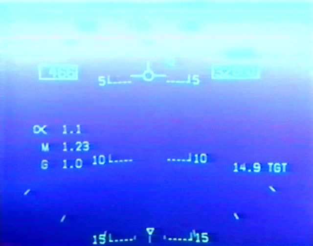
At my request, Dave selected the AIM-7 Sparrow HUD mode,
AIM-120 AMRAAM
being absent in this software load. This presented a circle on the HUD
and left MFD, with a range arc and supporting data.
Much to my disappointment, uncooperative afternoon air traffic
denied
me the opportunity to play BVR shooter! I looked forward to the
possible
opportunity to practice a BVR engagement against a fat juicy RPT heavy
out of Tullamarine, alas I was unlucky.
I slowed to 250 KIAS and ducked under the 2,500 ft CTA step to
position
for an oblique downwind join, while Dave made the radio calls and
demonstrated
an air-air track with AIM-9 selected, against an aircraft in the Avalon
circuit.
2.6 In the Circuit
I joined the circuit on an oblique late and very wide downwind
for
runway 18, pulling back the power to slow down through 200 KIAS down to
about 150 KIAS at 1,500 ft and turning into a very wide base for a long
final. The aim was to get plenty of time to set up for the proper
glideslope.
Dave lowered the gear and flaps, as only emergency gear deployment
controls
are present in the aft cockpit. There was no perceptible pitching
during
undercarriage deployment.
Dirty, with flap deployed, at 125-130 KIAS the aircraft is
very smooth
and stable and exceptionally easy to point very precisely. The HUD mode
for landing has a very nice extended synthetic horizon line, and a
glideslope
vector marker as well as the velocity vector symbol. Dave trimmed the
aircraft
properly.
My power adjustments were producing an excessive sink rate
entering
finals, and on Dave's instructions I added power to get back on the
glideslope.
With a light crosswind from the east, very little rudder was required
to
get the few degrees of crab angle for a good centreline on finals. With
the forward cockpit ejection seat blocking my view, the bulging sides
of
the canopy provided enough forward view to lean sideways and keep the
aircraft
comfortably on the centreline. With HUD symbology on the left MFD, the
glideslope pipper is easily tracked to verify whether the descent is
above
or below the required glideslope.
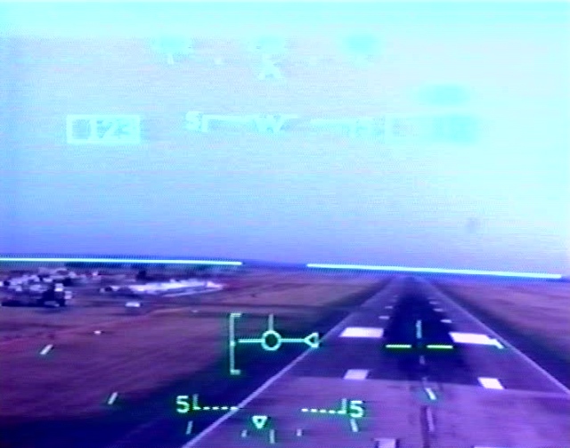
Short
finals,
Runway
18, Avalon. Note the crab angle.
As we crossed the threshold I began to raise the nose slightly
to flare
and was promptly told to drive it in - we hit the runway at a nominal
sink rate of around 10 ft/sec, all of which was absorbed by the sturdy
naval undercarriage. The aircraft swayed about 5 degrees in a slight
rolling
motion but within a couple of seconds righted itself as we rolled along
18. Rolling along the runway, Dave instructed me to apply a little
right
and then left rudder input to try out the nosewheel steering, which is
quite firm. With about half of the runway gone, Dave applied mil power
and on his call I gently rotated the aircraft off the runway.
We climbed up to about 1,500 ft in the circuit, and turned
smoothly
on to downwind. The second circuit was considerably tighter, a large
pelican
sighted at our altitude during the turn to final thankfully did not
require
an evasive manoeuvre to avoid. Again, the aircraft's smooth and stable
handling in landing configuration made the circuit easy to fly
precisely.
Another no-flare touchdown, upon which Dave took the controls, applied
mil power, rotated and then accelerated along the runway to sharply
pull
up in a 40 degree climb at 125 KIAS. As the aircraft hit 1,000 ft, Dave
rolled the aircraft on its wingtip and flew a very tight join on
downwind
for a very tight circuit and descent on to finals for a showpiece
landing.
We stopped at about one third runway length, where I was given a
demonstration
of the carrier optimised nosewheel steering. The aircraft swung around
almost on the spot to point downwind for a backtracking taxi to the
parking
area.
The flight was over, and in minutes I would have to part with
an aircraft
which was a sheer pleasure to fly, even at the very edge of the
envelope.
We taxied back with 1.1 hrs elapsed and 4,000 lb of fuel
remaining.
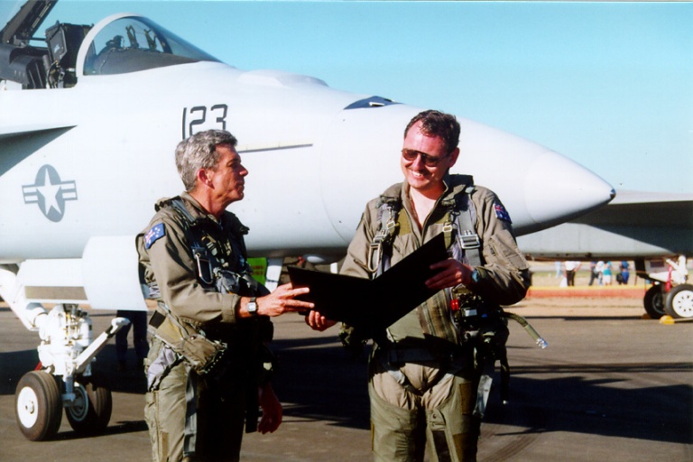
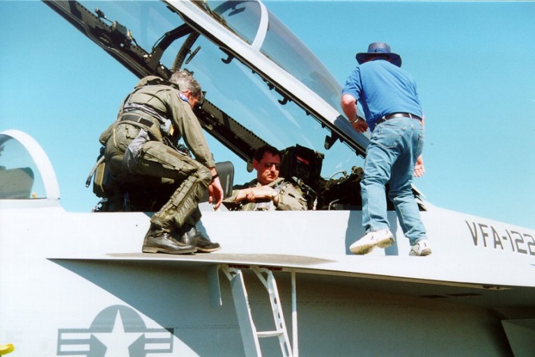
Boeing's
F/A-18E/F
Chief
Experimental Test Pilot Dave Desmond and the author,
post sortie.
2.7 Observations
The Super Hornet is a fighter with exceptional handling
qualities,
even by modern fighter standards, which even a novice can handle
comfortably
and with confidence at the edge of the low speed manoeuvre
envelope.
The point which Boeing and the US Navy have made most
convincingly,
is that the aircraft's flight control software is so robust that even a
beginner on the type can fly it without embarrassing himself too badly.
Sceptics should note that test pilot comments about fighters with this
generation of flight controls being as easy to fly as a Cessna 172
are
indeed correct. There is no room for argument here, as I had the
opportunity
to observe first hand!
In the hands of an experienced combat pilot, such flight
control software
means that the pilot can be wholly focussed on the furball in progress,
and need not devote any thought to pushing the aircraft past the edge
into
a uncontrolled departure and resulting risk of a ground impact or
successful
enemy missile shot. The importance of a substantially departure
resistant
aircraft, especially if encumbered with stores, cannot be understated -
carefree handling translates directly into combat effectiveness.
In a low speed post-merge manoeuvring fight, with a high
off-boresight
4th generation missile and Helmet Mounted Display, the Super Hornet
will
be a very difficult opponent for any current Russian fighter, even the
Su-27/30. The analogue and early generation digital flight controls
with
hard-wired or hard-coded AoA limiters used in the Russian aircraft are
a generation behind the Super Hornet and a much more experienced pilot
will be required for the Russian types to match the ease with which the
Super Hornet handles high alpha flight regimes.
The reports emanating from carrier landing trials performed in
the US
cannot be disputed, the aircraft is a sheer delight in the circuit and
will take much of the anxiety out of night and bad weather traps,
especially
for nugget fighter-attack pilots.
The cockpit ergonomics build upon two decades of Hornet
experience,
and make for a very comfortable and easy to use cockpit environment.
Again,
a novice pilot will find the MFD modes easy to navigate and easy to
follow.
The colour moving map display makes navigational orientation
ridiculously
easy, against the mental chores of VOR/DME/TACAN, radar mapping and
INS/map-on-the-knee
navigation. The prospect of MIDS/RWR/radar/IFF tracks being overlayed
on
the moving map will take much effort out of maintaining wider area
situational
awareness.
The radar is very easy to use in MMTI, GMTI and SAR spot
mapping modes,
and provides an excellent tool for highly accurate all weather maritime
strike, littoral strike and battlefield interdiction operations. In
particular,
the ability to interleave MTI and surface mapping modes is
exceptionally
useful for resolving and identifying moving surface targets of
opportunity.
In conclusion, the reports of the Hornet's exceptional high
alpha handling
characteristics are provably correct. Established Hornet users should
not
be disappointed by this aircraft!
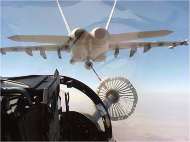
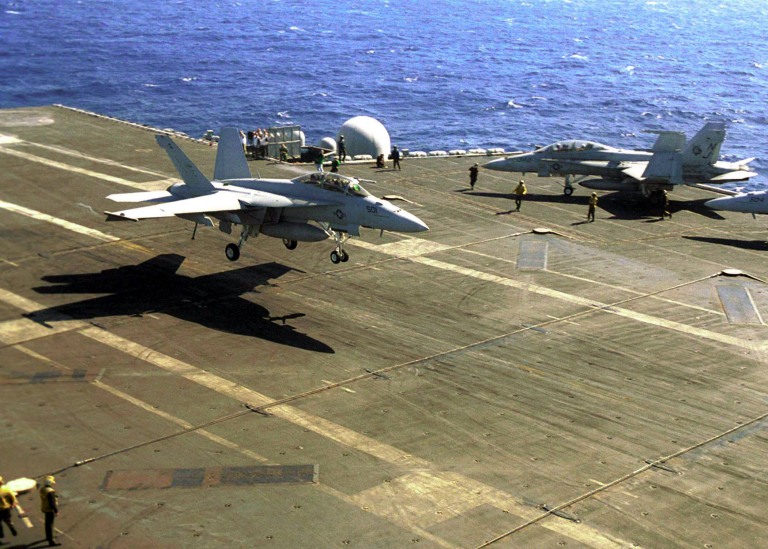
A key role in USN
service
will be tactical tanking, using a buddy
refuelling store. With the loss of the KA-6D fleet and impending
retirement
of the KS-3 Viking tankers, the F/A-18E/F will become the sole carrier
based tactical tanking asset. Unlike the KA-6D and KS-3, an F/A-18E/F
gas
truck is not a tanker to be trifled with by hostile fighters (Photo
Boeing)
3 Acknowledgements
Thanks to Boeing and the US
Navy F/A-18E/F Program Office
for their efforts in enabling the author to fly the F/A-18F, and
especially
Boeing's F/A-18E/F Chief Experimental Test Pilot Dave Desmond.
Imagery - US Navy, Boeing.
|


 [Click for more ...]")