|
||||||||||||||||||||||
 |
||||||||||||||||||||||
 |
 |
 |
 |
 |
 |
 |
 |
|||||||||||||||
 |
 |
 |

|
 |
 |
 |
 |
|||||||||||||||
 [Click for more ...]") |
||||||||||||||||||||||
| Last Updated: Mon Jan 27 11:18:09 UTC 2014 | ||||||||||||||||||||||
|
||||||||||||||||||||||
|
||||||||||||||||||||||
|
||||||||||||||||||||||
|
|
|
|
|
|
|
|
|||||||||||||||
|
|
|
|
|
|
|
|
|||||||||||||||
|
||||||||||||||||||||||
| Last Updated: Mon Jan 27 11:18:09 UTC 2014 | ||||||||||||||||||||||
|
||||||||||||||||||||||
| AEW & AWACS | |||
|
|||
Part
1 - The Issues
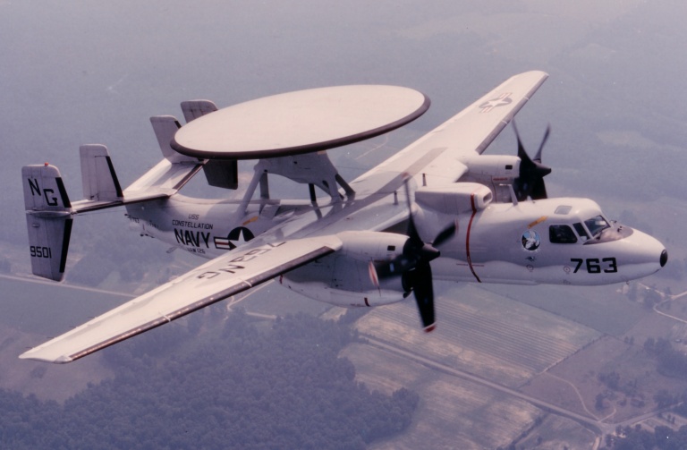
Kim Beazley's decision to proceed with the acquisition of Airborne Early Warning aircraft for the RAAF is one which informed observers will all agree to be long overdue. This journal argued strongly for the acquisition of AEW aircraft a half a decade ago and needless to say none of the issues under examination at the time have changed. While it is nice to see one's assertions vindicated the issue is now one, of which system is best suited to the RAAF's unique operational environment. The RAAF is facing a non-trivial decision. Modern Airborne Warning and Control/Airborne Early Warning/Airborne Surveillance Warning and Control (AWACS/AEW/ASWAC-the reader is free to choose, we will use the appelation AEW without implying a specific design) aircraft are complex systems integrating a large look-down radar, secondary radar (IFF), Electronic Support Measures (ESM) and a broad array of voice and data communication equipment, all of these carefully traded off to support a specific air defence environment. AEW emerged in the immediate post war period when the US Navy, responding to the painfully learned lessons of defending against the kamikaze, deployed its TBM-3W Avengers. The idea of carrying a search radar on an aircraft stemmed from a fundamental geometrical limitation of surface based radar, its inability to see over the horizon. From a warship, subject to the height of the antenna, the radar horizon is of the order of 15nm away or less with diminishing antenna height. This constraint and the less demanding ocean clutter environment made for a large payoff in the use of AEW at sea, putting the radar antenna onto an aircraft being the simplest way of extending the radar horizon. The USN and RN adopted AEW very promptly and deployed AN/APS-20 radar equipped AD-3W, AD-4W and AEW.1 Skyraiders on several carriers, while the USN and USAF fitted the radar to long range land based WV-1/2 and EC/RC-121 C/D derivatives of the Lockheed Constellation. These APS-20 based systems represent the first generation of AEW systems and saw extensive use well into the seventies, when the USAF deployed its C-137(707) based E-3A and the USN phased out the last of its land based AEW in favour of carrier based E-2B/C Hawkeyes. Carrier based AEW has had a colourful history with the USN deploying the AD-3W, AD-4W, E-IB Tracer and finally the very successful E-2B/C family, while the RN transplanted its APS-20s into the Gannet AEW and subsequently passed these radar sets to the RAF where they equipped the long serving Shackleton AEW. At this instant in time, AEW has been widely recognised as a key part of a modern air defence system, with the E-2C deployed by the USN, Japan, Israel, Egypt, Singapore and sought by Pakistan, the E-3A/B/C deployed by the USAF, NATO, Saudi Arabia and on order with the RAF and Armee de I'Air, the P-3 AEW&C deployed by US Customs, the II-78 based Mainstay deployed by Russia's IA PVO and the Madcap under development. Proposals involving 707, C-130 and other airframes seem to be
very common in the late eighties.
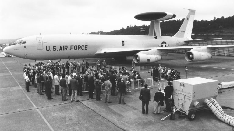
Boeing
E-3A AWACS (Boeing
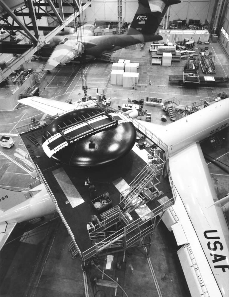
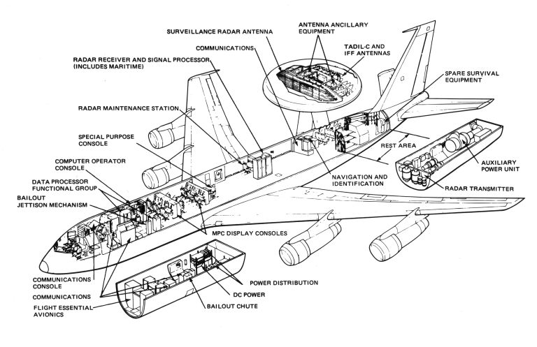
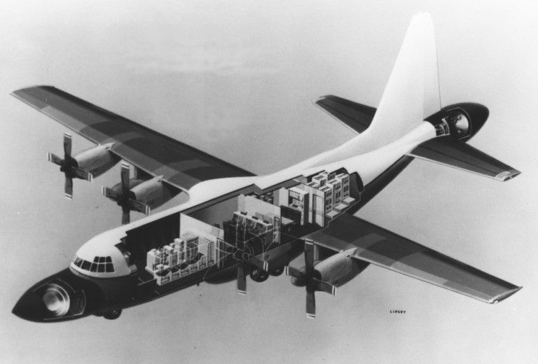
images). AEW - A System Perspective The intensity and pace of the modern air battle with its emphasis upon the disruption of Command, Control and Communications (C) facilities with electronic warfare techniques and exploitation of low level penetration to targets, dictates the use of AEW if a successful air defence umbrella is to be maintained. The ability of an AEW platform's look-down radar to strip away the sanctuary of terrain following flight, removes a key advantage possessed by the attacker, surprise. To fully exploit the high ground held by the AEW platform, it is however, essential that secondary radar (Identification Friend Foe (IFF)) be carried to manage own aircraft and extensive voice and data communication systems be installed to support friendly aircraft and surface based defences. To this must be added ESM, sophisticated radar warning receivers, which allow passive long range detection of inbound threats and provide the ability to identify non-cooperating tracks (ie those which ignore IFF). With several hundred tracks generated by the radar, IFF and ESM, the task of correlating these tracks and maintaining track histories, demands automation and hence powerful computers must be carried. These will interface to the operators via sophisticated consoles, while considerable mass storage will be required to support operation and log track histories. This hardware alone is complex and demanding of volume, payload, cooling capacity and power, all of which in turn, place demands upon the airframe and powerplants. To this complexity however,must be added the software, some of which carries out specialised tasks such as signal processing and most of which controls the radar, IFF, ESM and C hardware while driving operator consoles and maintaining track histories. AEW is therefore expensive to design, build, deploy, support and train aircrew for, this is the price an air force must pay for a priceless tactical advantage. Airborne Pulse Radar and Clutter The radar system of an AEW platform is the key to much of its capability and in the final analysis, a measure of its worth tactically. The look-down performance of such a radar at long ranges over land mass, is usually seen as the determining performance criterion when judging an AEW platform, weaknesses in this area led to the much publicised demise of the RAF's BAe/GEC Nimrod AEW.3 aircraft three years ago. Modern AEW aircraft carry two forms of radar, Moving Target Indicator (MTI) and Pulse Doppler (PD), both of which are essentially pulse radars with additional signal processing to exploit the Doppler effect in locating targets otherwise hidden by surface clutter. Lockheed AMSS proposal. Lockheed's Advanced Multimission Sensor System proposal for a Carrier based AEW aircraft is interesting as it employs a fixed three sided dorsal radome covering what would be three phased array antennas. Phased arrays are built up of thousands of miniature receive / transmit elements which allow nearly instantaneous electronically controlled pointing of very low sidelobe beams, with good frequency agility. This will provide high resistance to jamming while also defeating most Anti-Radiation Missile seekers which home in on a radar's sidelobe transmissions.
Radar in the general case involves the detection of targets by illuminating them with an electromagnetic wave and then listening for the reflection (echo) of this wave from the target. Because electromagnetic waves travel at a constant speed (of light), numerous techniques can be used to then determine the range of the target (and hence Radio Detection And Ranging). A radar always has three basic components, a transmitter chain, an antenna and a receiver chain. The transmitter chain is a high power source of electromagnetic signal and it can be built as a high power oscillator (typically pulsed Magnetron) or as a MOPA (Master Oscillator Power Amplifier) chain using typically Travelling Wave Tubes. The waves it produces must be focussed into a beam and pointed in some sought of direction, this is one of the functions of the antenna. The beam then propagates through space, hits a target and some of the power in the beam is scattered back in the direction of the illuminating radar antenna. Because the wave weakens with distance covered (inverse square law) and the target reflects only a small fraction of the impinging wave, the return (echo) will be very faint by the time it arrives back at the radar antenna. Here is where the antenna comes into play again, focussing and concentrating the faint return at the input of a sensitive receiver termed a front end. The received return signal is then manipulated in a number of clever ways, amplified substantially and in the simplest case fed to a Cathode Ray Tube which displays an image synchronised to the motion of the antenna. The observant reader will note that this notional radar is transmitting while receiving through a single antenna, in practice this is seldom done as the amount of power leaking from the transmitter feed into the receiver feed would blind the receiver to the weak echoes it is listening for. Real surveillance radars are built as Pulse radars. A pulse radar transmits only for a very brief time, a short burst (pulse) usually about a microsecond or so in duration at a time, after which it listens for echoes as the pulse propagates away. Because the Pulse is receding away from the radar at a constant speed, the time elapsed from the instant the pulse was sent to the time an echo is received, is a clear measure of the line-of-sight distance to the target. The next pulse can only be sent after a time which is equal to the round trip delay of a pulse reflecting from a target at the limit of the radar's detection range (given by transmitter power, antenna gain and receiver sensitivity). If a pulse were sent any earlier, the echo of the first (ie; preceding) pulse from a distant target could be confused with an echo of the second pulse from a close target (the reader is advised to sketch this). The time gap between pulses is termed Pulse Repetition Interval (PRI), its inverse is an important parameter termed Pulse Repetition Frequency (PRF). Low band long range surveillance radars have PRFs typically of hundreds of pulses per second (or Hertz [Hz]). Needless to say PRF is a distinctive signature betraying the identity and operating mode of a radar to any eavesdropping RWR. This generic pulse radar is typical of early systems and performs only when the background beneath the target is clear airspace. If such a radar looks at a target flying above eg; a large hill, the return from the hill will be far stronger than the return from the aircraft and the target will be obscured. The term used for these unwanted echoes from Mother Nature's splendour is clutter. Needless to say clutter was a cause of great pain to early radar designers and has only been dealt with adequately in the last two decades. Airborne pulse radars are particularly vulnerable to clutter which most effectively hides low flying targets, these radars are usable only against targets at the same or at a higher altitude. Techniques for dealing with clutter exploit in one or another way, the Doppler effect (the frequency of a wave reflected off an approaching object is increased, a receding object decreased). The simplest radar which can detect an object in clutter is a Moving Target Indicator radar. An MTI is a pulse radar which will compare the returns over two or more pulse repetition intervals. Any target which is, moving relative to the radar will register a change in a signal parameter (phase in a coherent MTI), whereas the background clutter is unchanged. Clutter cancellation is then carried out by subtracting the returns from the two successive intervals. In practice cancellation can be accomplished in hardware (delay line cancellers or analogue bucket brigade chips) or by algorithms in software. MTIs operating at a constant PRF suffer a fundamental weakness, they are blind to targets with particular relative velocities (which incur phase shifts of multiples of 180 degrees) and are said to be ambiguous in velocity. Modern MTIs transmit multiple staggered PRFs such that the blind speeds at each PRF are covered by other PRFs. An alternative family of techniques for dealing with clutter fall under the designation of Pulse Doppler radar. PD radars employ substantially more complex processing than MTIs. In a PD radar the returns containing targets and clutter are fed into a bank of Doppler filters, each of which is tuned to a particular frequency ( - Doppler -> speed). In this fashion targets with given speeds register as outputs from given filters, which may be implemented in hardware or software. In this basic form, a PD radar cannot resolve target range (of MTI) and is said to be ambiguous in range. Further manipulation is thus required to define range, this is usually done by dividing the pulse repetition interval into slices termed range cells, the Doppler filter bank is then selectively fed during a given range cell. This is termed range gating and results in a set of filter outputs indicating the velocity of any targets detected in that range cell. Because typical Pulse Doppler radars operate at medium to high PRFs (usually thousands of Hertz) the above technique becomes ambiguous in range and multiple staggered PRFs are used (of MTI) together with some clever processing to decide which actual range the target is at (it will appear in different range cells at different PRFs). Pulse Doppler radars are usually considered superior to MTI in the detection of low flying targets in heavy ground clutter, it is the preferred technique used in modern fighter air intercept/fire control radars eg the AN/APG-63, 65, 66, 67 and 70. In current PD radar most processing is carried out by a dedicated digital computer termed a digital signal processor, usually executing a powerful algorithm termed a Fast Fourier Transform to convert the digitised stream of return samples into something more manageable by other algorithms. DSPs are very flexible in that the algorithms used can usually be rapidly changed by swapping read only memory (ROM) chips, thus rapidly countering an opponent's jamming technique if necessary. Airborne Doppler Radar The carriage of radar on a aircraft introduces a wide range of problems. The motion of the aircraft dictates that the antenna be stabilised in pitch, roll and yaw, to provide a stable jitter-free picture, this becomes a major effort with increasing antenna size and weight. The other major problem area is of course clutter. A moving aircraft will itself have a Doppler relative to the Earth's surface, hence shifting the nett clutter return in frequency. At first glance this would be a simple problem to tackle, by filtering out all of the return with the expected ground Doppler , which is given by the aircraft's instantaneous ground speed and the direction the antenna is pointed in. Reality isn't so simple though, as antennas are not ideal and will at best try to produce a tight beam, spilling out power in weaker off-axis beams termed sidelobes (and receiving unwanted weaker returns from the direction of these beams). As is apparent the different directions the sidelobes point in, will result in different Doppler shifts as compared to the antenna mainlobe, with the result of course that the clutter produced by the sidelobes will be difficult to remove. This is further complicated by the unfortunate reality that the aircraft's airframe itself, interacts with the mainlobe and sidelobes, reflecting these off in directions very different to the axis of the antenna. Needless to say, this further complicates the rejection of clutter and imposes the need for very careful antenna placement on the airframe. This problem is exacerbated where the radar operating wavelength is large, relative to the antenna size, as the sidelobes are larger (in general the larger the antenna relative to the wavelength, the tighter the beam). It is for this reason that PD radars designed specifically for overland look-down performance, use shorter wavelengths (typically E/F band for AEW with 3-8m antennas and I/J band for Air Intercept with 1 m or smaller antennas), even if this incurs a major cost penalty due to more expensive (faster) transmitter chains and receivers (faster, more sensitive). This aspect of performance can be tricky to assess, in that longer wavelengths do tend to provide stronger and more stable returns (resonance region radar cross section, see TE May 1987) with better skin depth penetration of radar absorbent (stealthy) skins, as compared to shorter (microwave) wavelengths where returns scintillate (optics region RCS) with target aspect. The now you see it, now you dont' aspect of a scintillating target imposes the need for a capable data processing system with sophisticated tracking algorithms (Kalman filtering techniques are commonly used). The decision to use a given wavelength and antenna configuration is thus not trivial, with substantial cost and system complexity penalties attached to the use of higher performance microwave band antennas.All of these factors impact upon the physical installation within the aircraft. More sophisticated electronics tend to consume more power, require more cooling and occupy more space, while costing more and requiring more maintenance by better qualified personnel. While discussing performance tradeoffs, resistance to hostile jamming ie ECCM performance must be considered, particularly where one is up against a clever opponent. Antennas with large siddelobes are inherently vulnerable to high power noise jammers and false target generators, while a modern AEW radar must have a measure of frequency agility, the ability to quickly tune away from a jammer, preferably automatically. ECM is however, a non lethal threat which can be fought with clever ECCM, the proliferation of high performance Anti-Radiation Missiles will eventually make life quite difficult for conventional AEW platforms. The only real counter to these, is the use of sophisticated Low Probability of Intercept (LPI) techniques (pseudorandom signal formats and scan patterns) requiring phased array antennas and very sophisticated signal processing, scan control and data processing. This will result in further complexity in hardware and particularly software, but with a major pay off in resistance to jamming and an ability to disrupt tracking by an ARM seeker. IFF, ESM, Data Processing and C3 Systems Given that a radar of such capability is successfully fitted to an airframe, it must be integrated with a suitable data processing system, software and operator consoles. The software running on the computer(s) at the core of this system, will command the radar and its dedicated signal processor to given operating modes, while receiving and managing target track information produced by the radar. Tracks are then displayed on operator consoles. Target tracks are usually identified or tagged, depending on their IFF and ESM status, a task termed association which involves matching up radar target tracks with IFF tracks and ESM bearing/type readings. IFF, which relies on coded responses by transponders carried by friendly aircraft, is an essential comple ment to an AEW radar, providing positive identification of responding friendly aircraft. IFF interrogator antennas are usually mounted back to back with radar antennas in rotodomes or on axis with conventional (eg offset parabolic antennas), sharing access ducts and implicitly antenna motion stabilisation. Electronic Support Measures are an often overlooked complement to an AEW platform's primary and secondary radar, but are becoming increasingly important in a modern air battle. ESM equipment comprises sensitive direction finding radar warn ing receivers, coupled to an extensive software threat library and able to produce bearing and type tracks in a format readable by the data processing software, passively identifying the source of a transmission at ranges of the order of twice that of radar with comparable receive sensitivity. Where a target is not responding to IFF interrogation and is therefore potentially hostile, ESM identification can provide confirmation of, or disprove its status hence avoiding tragedies such as the Persian Gulf Aegis incident, this unfortunate event provides a clear illustration of the pitfalls implicit in air defence operations where decisions are based on the outputs from a single sensor, eg radar. Complete target identity information is today unattainable, given the state of the art in sensors, but well implemented radar/IFF/ESM integration can go a long way in resolving uncertainties. Association of radar, IFF and ESM tracks can take place prior to the radar track information being passed to data processing or be done in software by the data processing system, which will typically create a track file on mass storage (disc or drum in older machines), the file containing target parameters and being maintained as long as the target is tracked. It is worth noting, that any reasonable AEW system will demand considerable mass storage (disc/drum and magnetic tape) to maintain tracks in a dense signal environment, while logging histories on mag tape drives. USN Grumman E-2C Hawkeye. Israeli Air Force E-2Cs played a key role in the crushing defeat of Syria's fighter and SAM forces over the Bekaa Valley in 1982. Initially these aircraft employed ESM to pinpoint SAM and radar sites, after these were destroyed in missile and bomb attacks the E-2Cs coordinated and controlled a series of air battles which resulted in the loss of over 80 MiGs for no Israeli losses in air-air combat. The limitation imposed by the data processing is in the number of tracks which can be maintained before the computer runs out of horsepower and the system saturates, resulting in software crashes or tracks disappearing off screens. The failure of GEC's APY-920/Nimrod was due in part to problems in this area, with highway traffic incorrectly tagged as real targets saturating the data processing computer. C3 and its associated management systems are another key component of an AEW system, providing voice communications and digital datalinks to both fighter aircraft and surface defences, the latter of particular importance, as they can feed target track parameters directly into the fire control systems of interceptors and SAM/AAA systems, thus very tightly coordinating defensive fire. In an environment where inbound bombers can successfully jam smaller AI radars, the superior ECCM performance of a sophisticated AEW radar can allow a successful intercept (the E-2C/F-14/AWG-9 provides for fully automated intercepts). The integration of data Processing and C3 systems is thus of particular importance if a user seeks the full benefit of the AEW system. Deficiencies in this area could bottleneck the flow of vital information to the place it is most needed, the fire control system of a defending interceptor. It is readily apparent the functional utility of an AEW system depends as much upon the performance of its radar as upon the capability of its IFF, ESM, C3, computers and as upon the capability of the software which ties it all together. Aerodynamic Performance and the Airframe While the systems carried on an AEW aircraft largely determine the overall system capability, the airframe and its aerodynamic performance must be well matched to the mission electronics. An airframe must have the internal volume to carry substantial fuel, to fit the large radar transmitter chain(s), associated power supplies, the receiver, IFF, ESM electronics racks, the computers and associated mass storage devices and the opera tor consoles, while providing inflight maintenance access to repairable critical systems, adequate space for active crew stations and relief crew accommodation where applicable. Aircrew accommodation is particularly important, as fatigue will rapidly degrade operator performance. If missions are longer than of two to three hours duration, operators will have to be rotated for breaks. Inflight maintenance access to electronics racks must also be considered under these circumstances, as it could prevent a mission abort in the event of an inflight repairable failure not covered by redundancy. Accessibility in general helps to reduce down-time and should never be overlooked. Another important aspect is the capacity of the onboard electrical power generators to supply the vast amounts of power required for the transmitters, while the engines are at cruise/endurance thrust settings. Higher thrust settings penalise endurance. Powerplant loading must also consider power required for cooling the electronics and transmitter tubes, this can be substantial in itself. The generators are ideally redundant and may have to be separately allocated to the transmitter power supply and remaining electronics supplies, to ensure that the computers and receivers get clean electrical power without interference leaking through (thus preventing software crashes or other problems). Powerplant loading thus will affect aerodynamic performance, which alone is a key factor in determining the system's capability. The most important aerodynamic performance parameters are altitude on station and of course endurance. Altitude on sta tion determines the distance to the radar horizon and thus the limit upon the detection range for low level targets, otherwise given by the performance of the radar, in particular its signal processing. Understandably detection range for targets above the horizon is greater and determined much by the performance of the receivers. On station altitude is constrained by flat (skidding) turn performance and minimum powerplant fuel consumption (to maximise endurance), for a turbojet/turbofan near the tropopause (cca 35,0000 ft) and for a turboprop usually between 20,000 to 30,000 ft (props require increasing power with altitude, which counters the improvement in fuel consumption with altitude). Where look-down detection range is a priority a jet powered aircraft has an advantage, as is apparent from a mission profile. A typical mission profile will involve a climb and then cruise (cruise climb if a jet) to station, where the aircraft enters a racetrack pattern which it maintains typically until its allocated fuel load is consumed, after which it will cruise back to its operating base. Inflight refuelling offers a large payoff where the distance to station exceeds a hundred or so nautical miles, as the fixed overheads in fuel and time incurred during a return/refuel/turnaround are reduced, typically by 50% where inflight refuelling has doubled time on station. This will reduce the number of AEW aircraft required to provide continuous coverage on a given station. An AEW aircraft on station will usually control two or more standing Combat Air Patrols (CAP) in racetrack orbits to the left and right of the threat axis (an imaginary line between the defended target and inbound threat) with the risk to the AEW aircraft determining how far toward the threat the AEW station will be. Where the enemy uses high performance fighters with long range radar and AAM/ARMs, the AEW aircraft will have to be stationed well behind the CAPs which reduces warning time and the width of the interception barrier (an imaginary line perpendicular to the threat axis, through which no hostile should pass). Where AEW detection range is poor, risk must be traded against the need to stop low level penetrators firing standoff Precision Guided Munitions, both of which are the most difficult class of targets to detect and consequently requiring as forward an AEW station position as possible to maximise the warning time. If CAP is unavailable and ground alert interceptors are used, the interceptor's dash to station time delay must be accounted for and the AEW aircraft stationed closer to the defended target, with an inevitable reduction in the interception barrier width (here again tankers prove their worth by allowing extended duration fighter CAP). It is very clear therefore that the choice of AEW radar and airframe will have to be carefully considered against the various operational scenarios likely to be encountered, these factors illustrating the constraints which have led various air forces to develop very different airframes and radars for the role. Part II, The Australian Perspective will be presented in the May edition of Australian Aviation. PART II - The Australian Perspective
These may range from high level threats such as AV-MF and VVS Bears and Backfires, staging from Cam Ranh Bay and flying peacetime surveillance/recce and wartime strike missions, through Indonesia's F-16 and A-4 tactical jets which could be expected to play a major role in any serious regional dispute, down to general aviation aircraft used to smuggle drugs into the country or other items (eg; wildlife) out of the country. While these winged intruders constitute a potential and real problem, one cannot overlook the environmental threat posed by Indonesian fishing vessels often caught plundering the rich fishing areas of the North and North-West, this activity is pursued with obvious contempt for Australian quarantine procedures. Clearly the problems of illegal fishing, immigration and drug running are the most pressing at this instant in time, the potential wartime threat of air strikes and supporting recce however, must not be dismissed, given the rapid economic growth in the North and North-West. It is fair to say, that the fighting in the Persian Gulf and recent disasters in the North Sea, graphically illustrate the vulnerability of onshore and offshore oil/gas installations to Anti-Shipping Missile (ASM) attack. The Barrow Island area and Withnell Bay facilities and the North Rankin Platform, are thus lucrative targets for a serious opponent. It is not unreasonable to surmise, that the threat alone of such attack (potentially stopping 30% of our national natural gas production capacity) could serve to tie many of the RAN's area defence SAM firing vessels to air defence picket duty covering these sites, thus effectively reducing RAN resources available for offensive and other defensive operations. This situation will be exacerbated if the Timor Sea oil/gas wells are developed for production. To these targets we must add the expanding RAAF and Army infrastructure in the Northern Territory and North of WA and of course Cape York. Were the proposed spaceport to go ahead, it would represent a target of considerable propaganda value. To defend the North and North-West the RAAF is expanding a chain of airfields, some of which are established and several of which are new, including the hub of Northern operations, Tindal near Katherine in the NT. To the West Learmonth, Port Hedland and Derby, to the East Gove, Weipa and Cairns, these airfields would support detachments of F-18 aircraft from the squadron home based at Tindal. These aircraft would receive inflight refuelling support from tankers operating or staging from Darwin/Tindal and thus, could carry out intercepts several hundred nautical miles off the coast if necessary, alternately Combat Air Patrol endurance could be stretched considerably. Limitations in numbers of aircrew and support personnel would however dictate ground alert rather than standing CAP which will impose a need for good early warning of inbound hostiles. While the basing of interceptors close to targets is an important aspect of air defence, it is of limited value without extensive low level radar coverage, command posts and associated C3 facilities. Long range early warning of inbound threats will be provided by the Jindalee Over The Horizon Radar (OTHR). OTHR is invaluable as it can detect and track low flying aircraft and ships at ranges beyond 1500nm. It has limitations though, as its accuracy in range and azimuth locate a target only within an area of several nautical miles with no height finding capability, with performance fluctuating subject to ionospheric conditions. OTHR will thus provide an indication of an inbound threat and its location with an accuracy that may or may not provide for a successful intercept. As it lacks the ability to identify an aircraft from IFF/ESM/flight profile, its usefulness for the close control of interceptors is limited, more so since an extensive network of communications relays would be required to control air defence aircraft (a HF datalink is another alternative, penalised in performance however by ionospheric conditions). These gaps in capability are filled with an AEW aircraft, which carries ESM, IFF and a centralised C3 network with it, regardless of the state of the ground based infrastructure it is defending. The capabilities of AEW and OTHR are thus clearly complementary, with OTHR providing up to several hours of warning, AEW aircraft and interceptors can be positioned to provide the best pos sible coverage of targets accessible by the inbound hostile(s). The AEW aircraft would then identify the threat and control intercepts taking advantage of its on board systems. It must be stated that proponents of either system who reject the alternative have not understood the difficulties involved in covering the vast area of the North and North-West with a handful of fighter aircraft.
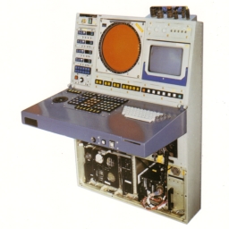
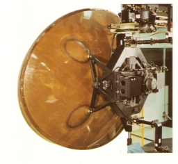
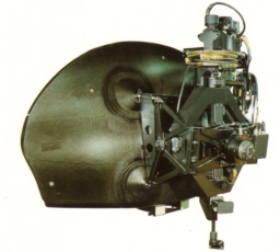
RAF BAe Nimrod AEW.3. The AEW Nimrod was an
innovative
British design which ran into development problems and in 1986 was
cancelled in favour of the larger Boeing E-3/Westinghouse APY-2 AWACS
system. Many of the Nimrod's troubles stemmed from the choice of an
airframe too small to support the space, cooling and power requirements
of a high performance AEW system resulting in major shortcomings in
range/ endurance. This was compounded by problems in antenna / receiver
/ radome performance and data processing capability. Lower images show
the operator console design, the original cassegrain antenna, and the
replacement offset paraboloid antenna design (GEC Marconi images).
It is expected that the AEW aircraft would be covering the two most sensitive areas in the North and North West, operating from Learmonth and Tindal, with other deployments possibly made to support operations in other areas if necessary. The air defence of the North and North West is uniquely characterised by a low density of possibly very sophisticated threats operating over land and sea, distances imposing the need for considerable range/endurance and an undisputable requirement for extensive C3 tied into a larger national air defence system. These C3 systems should have the ability to feed OTHR target track data to AEW aircraft for association with ESM, IFF and radar tracks while providing for the transfer of near real time tactical situation data into the national air defence system. The RAAF's eventual choice of AEW aircraft will thus have to not only account for airframe and radar/IFF/ESM performance, but also consider the capacity of the airframe and system hardware and software, to accommodate the hardware and software required for a tie in to what should eventually become the integrated National Air Defence and Airspace Control System. REFERENCES:
Readers with an interest in phased array radar principles are
directed to the following (very good) tutorial: Brookner E, Phased Array Radars, Scientific American,
February 1985. |
|||
|
|||||||||||||
|
|
|
|
|
|
|
|
||||||
|
|
|
|
|
|
|
|
||||||
|
|||||||||||||
| Artwork, graphic design, layout and text © 2004 - 2014 Carlo Kopp; Text © 2004 - 2014 Peter Goon; All rights reserved. Recommended browsers. Contact webmaster. Site navigation hints. Current hot topics. | |||||||||||||
|
Site Update
Status:
$Revision: 1.753 $
Site History: Notices
and
Updates / NLA Pandora Archive
|
|||||||||||||
|
|
Tweet | Follow @APA_Updates | |||||||||||
|
|
|||||||||||||
|
|
|||||||||||||