|
||||||||||||||||||||||
 |
||||||||||||||||||||||
 |
 |
 |
 |
 |
 |
 |
 |
|||||||||||||||
 |
 |
 |

|
 |
 |
 |
 |
|||||||||||||||
 [Click for more ...]") |
||||||||||||||||||||||
| Last Updated: Mon Jan 27 11:18:09 UTC 2014 | ||||||||||||||||||||||
|
||||||||||||||||||||||
|
||||||||||||||||||||||
|
||||||||||||||||||||||
|
|
|
|
|
|
|
|
|||||||||||||||
|
|
|
|
|
|
|
|
|||||||||||||||
|
||||||||||||||||||||||
| Last Updated: Mon Jan 27 11:18:09 UTC 2014 | ||||||||||||||||||||||
|
||||||||||||||||||||||
| THE LONG RANGE PENETRATOR | |||
|
|||
|
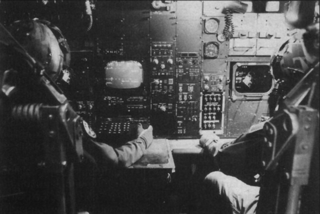
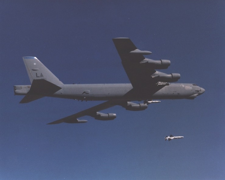
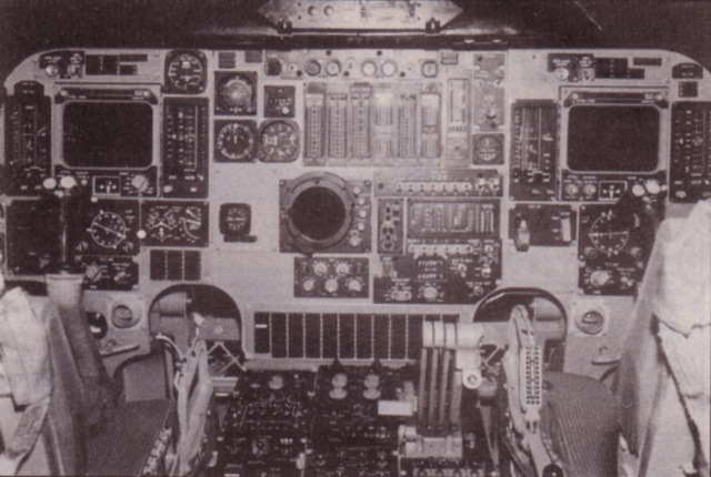
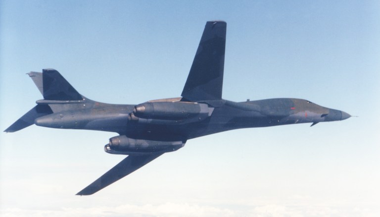
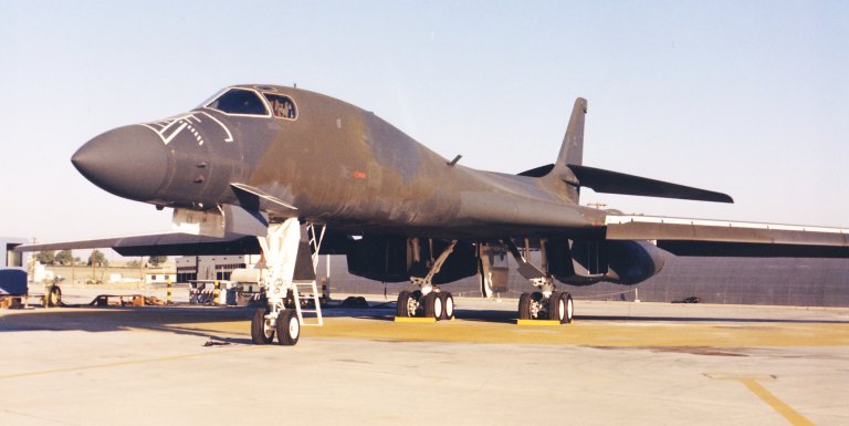
Part I The application of air power has traditionally been divided into tactical and strategic. The latter by nature has always involved the delivery of large bomb loads over substantial distances, with aircraft penetrating heavy defences in sustained bombing campaigns. Strategic bombing can be seen as a direct application of the often underrated Lanchester's Laws. A side may strengthen its position through the destruction of the opponent's production capacity while also tying up the opponent's tactical aircraft in the air defence role. This precludes their use over the battlefield and thus blunts the opponent's offensive capability by reducing concentration. For strategic bombing to be meaningful loss rates must be kept low, bombers and support facilities are expensive while the morale of the aircrew is critical to the effectiveness of such campaigns. Sustained loss rates above 3% will rapidly whittle away a force and render the exercise counterproductive. World War II saw the first major strategic campaigns, these being carried out by the RAF and USAAF. While the Americans preferred the brute force and initially very costly approach of precision daylight bombing, the RAF opted for night raids and in the process pioneered the use of Electronic Counter Measures (ECM) as a penetration aid. German air defences were countered with window (chaff), active radar and communication link jammers and radar warning receivers. Though many of the systems were highly effective, tactics were not always matched as a result of which loss rates were far from the optimum attainable (eg, the practice of penetrating with radar and IFF turned on provided the Luftwaffe with much valuable information). The difficulties were exacerbated by the limited accuracy of the bombing, which led to larger numbers of sorties required in turn increasing losses. The USAAF daylight campaign was also costly, until the arrival of the P-38 and P-51 escort fighters the bombers were at the mercy of the Luftwaffe and experienced enormous loss rates on longer sorties (eg, Schweinfurt-Regensburg cca 16%). The Luftwaffe however could not sustain its own attrition and eventually succumbed to a loss of manpower and dwindling fuel supplies. The nuclear strikes on Hiroshima and Nagasaki heralded a new era in strategic bombing. The long-range bomber became the basic delivery system for nuclear weapons and a whole generation of postwar bombers were developed to match the role. The USAF fielded the B-50, the B-36 and followed up with the turbojet powered B-47 and B-52. The RAF developed its V-force of Valiants, Vulcans and Victors. The Russians copied the B-29 (captured aircraft) and followed with the turboprop Tu-20 Bear and turbojet Tu-16 Badger and Mya-4 Bison. All of these aircraft would penetrate defences at high altitudes and speeds to defeat fighters while employing ECM to frustrate interception. In the nuclear age loss rates became less critical; only one to two sorties would be flown against a target. While conventional bombing could be discouraged by leaky defences through gradual attrition, the nature of a nuclear strike imposed the need for an airtight air defence if it was to be of any real use. The Surface to Air Missile (SAM) was thus developed to counter the strategic bomber. Saturation attacks with salvoes of missiles against single penetrating aircraft would sooner or later defeat the onboard ECM and score a hit. The difficulty of designing ECM to counter unknown weapon systems was an equally serious problem particularly in a Cold War situation. The early sixties also saw the initial deployment of all aspect semi-active radar guided air to air missiles (AAMs) carried by high speed interceptors. Clearly the days of high altitude high speed strategic penetration were nearing an end and a new approach was sought. Given the limitations of radar at the time, the obvious strategy was low level, high speed penetration and both the UK and the US developed aircraft to match the role. Britain's TSR-2 and the US F-111 were both dedicated high speed terrain following bombers, the former was killed off through political ineptitude, the latter survived and despite its age, now represents the cutting edge of NATO's deep strike forces. By the mid sixties emphasis had shifted away from tactical nuclear strikes while the Vietnam war put the new strategy of Flexible Response to the test. Although the war itself represented the classical case of political misapplication of air power it did see the historically (to date) final application of medium altitude saturation bombing and the debut of precision guided munitions and low level penetrators. The air war against North Vietnam saw the Americans in an unfortunate situation. Ill considered political decisions established numerous sanctuaries for both NVAF fighters and SAM sites. The NVA deployed incredible quantities of AAA (some sources suggest hundreds to thousands of barrels per square mile) and built up a very dense network of air defence radars taking advantage of politically imposed periods of no bombing. Until the 1972 Linebacker campaigns most raids were flown with tactical fighters such as the F-105 and F-4. These aircraft were supported by EB-66 tactical jammers and F-105/F-4 Wild Weasels (refer p21 July 86 AA) as neither the Thuds or the Phantoms had the jamming capability or low level terrain following ability to penetrate without assistance. The F-111A entered the battle during the Linebacker I campaign and quickly assumed the responsibility of attacking the most heavily defenced targets taking advantage of both darkness and foul weather. The aircraft demonstrated a loss rate of the order of 0.2% which clearly vindicated the use of expensive jammers, radar warning systems and terrain following radar. This was in stark contrast with the performance of the B-52 which was used to attack Hanoi and Haiphong during the December Linebacker II campaign. Given the amount of AAA present the B-52s attacked in formations flying at 30,000 ft, relying on powerful jammers to defeat the SA-2 SAMs launched by the North Vietnamese. The B-52D was the principal type used. These aircraft were configured for conventional bombing and were fitted with additional ECM systems. Typical loads were 42 750 lb M-117 bombs internally and 24 500 lb Mk82 bombs on pylons. The B-52D force was augmented by B-52G aircraft, which carried more internal fuel but were fitted with less capable ECM and carried a mere 27 750 lb bombs internally. Strikes were flown with three aircraft cells to increase the concentration of jamming power, most targets were attacked by streams of aircraft often approaching from different directions to confuse the SAM operators. The NVA put up a desperate effort and fired almost everything they had, in some instances the ECM was so effective that SAMs were launched at the B-52s blind. By the end of the eleven day air battle, fifteen B-52s were lost to the SAMs yielding a loss rate of 2%, it appears that up to 60 SAMs were fired for each B-52 kill. Two NVAF MiGs were destroyed by B-52 tailgunners. Linebacker II however was expensive, the logistical effort of supporting the B-52 force with ordnance, inflight refuelling, defence suppression and MiGCAP has yet to be matched. It was clear that medium altitude bombing would be just as costly as in WWII if a technologically sophisticated opponent was to be tackled, by the same token the effectiveness of the F-111A demonstrated the path for the future. SAC had certainly learned through the Vietnam experience and quite promptly shifted the B-52 to low level penetration while also pressing ahead with its B-1 A programme. The B-52G/H force today thus operates at low level and will continue in this role until the turn of the century. Weapons system operators work at the forward facing stations. The heavily rebuilt B-52G/H aircraft nowadays embodies an avionics suite that would have been undreamed of some forty years ago when Boeing initially launched the Stratofortress programme. With the introduction to service of the 8-18 through the late eighties and eventually the Northrop stealth bomber, the remaining B-52 force will primarily be employed as stand off cruise missile launchers against both coastal and maritime targets. B-52G Offensive and Defensive Systems An aircraft as large and unmanoeuvrable as the B-52 is almost totally dependent upon its onboard electronics when penetrating hostile airspace. Its eight turbojet engines have a large infra-red signature while its radar cross-section (RCS) is greater than that of any other Allied combat aircraft (the Russian Tu-20 Bear wins the prize for greatest RCS). Under these circumstances the B-52 will attack targets from stand off positions either with AGM-69 SRAM missiles or AGM-86 ALCM cruise missiles to avoid overflying heavily defended areas. Although this approach avoids SAMs, long-range lookdown/shootdown interceptors are a serious threat to the aircraft. Both the B-52G and the newer B-52H have experienced major avionics upgrades to improve survivability, involving both offensive and defensive systems. The B-52G's offensive systems aid in navigation and attacking of targets. The primary sensor is the multimode Norden APQ-156 Attack Radar which some sources suggest employs near real time synthetic aperture techniques (refer p61 March 85 AA) to provide high resolution ground maps. The radar is complemented by the ASQ-151 Electro-optical Viewing System (EVS) comprising a Hughes AAQ-6 Forward Looking Infra-red (FLIR) and a Westinghouse AVQ-22 Low Light TeleVision (LLTV) system. EVS imagery and superimposed symbology appear on cockpit CRT displays. The aircraft were fitted with a Honeywell SPN/GEANS inertial navigator from 1978 onward, the unit offers drift better than 0.1 nm/hr. Together with the nav-attack equipment these systems support both the pilots and the offensive systems operators, ie. the navigator and radar navigator/bombardier. The defensive systems are more complex and may be grouped
into
passive and active systems. Of the publicly known systems the passive
digital ALR-46 Radar Homing and Warning (RHAW) system is of great
importance. The RHAW analyses and identifies radar emissions which
impinge upon the aircraft, the ALR-46 handles 16 emitters
simultaneously
and can feed its output into other onboard systems (the ALR-46
supplants
the older APR-25 crystal video radar warning receiver). These are
essentially active jammers which may be grouped into deception jammers
and noise jammers. Noise jammers beam electrical noise into the
receiving arrays of hostile radar which results in a loss of receiver
sensitivity and thus shortened detection range - it is an essentially
brute force technique most effective at long ranges. The B-52G carries
the powerful Northrop ALQ-155/ALT-28 Power Management System/CW Noise
Jammer. The ALQ-155 comprises a set of automated set-on receivers
(these
may be locked on to a particular radar and then ensure that an
allocated
jammer is tuned in and timed correctly) which are cued by a RHAW system
on to a given threat radar. This approach allows optimum use of the
available jamming power which is generated by a set of ALT-28 noise
jammers. The ALT-28 employs high power backward wave oscillator tubes
which operate down to UHF frequencies, their output is fed into a set
of electronically steerable antennas and then beamed at the hostile
radar.
The prominent radome on top of the aircraft's nose covers an ALT-28 antenna. The ALQ-155 is complemented with an ITT ALQ-117/172 noise deception jammer of which two are carried. Installed under the Rivet Ace programme this I/J band system is power managed and can defeat monopulse systems. Subtler deception jamming is provided by the Motorola ALQ-122 false target generator and its associated ALT-16A solid state power amplifiers. The ALQ-122 will analyse hostile radar signals and then generate false radar returns with incorrect range and azimuth information, the unit is highly automated. The jammers are complemented with a set of ALE-24 chaff dispensers and the aft facing gun system. All aircraft were built with the four .50 cal guns in a tail barbette, these are aimed with the ASG-15 fire control radar. The upper search and lower tracking antenna radomes are easily distinguishable. A recent addition to the suite is the Westinghouse ALQ-153 tail warning radar which alerts the crew to aircraft approaching in the aft hemisphere. The defensive systems are operated by an electronic warfare officer and tail gunner. Clearly the amount of jamming power required to cover an aircraft the size of the B-52 is considerable and given recent advances in Warpac radar capability (eg, Fulcrum/APG-65ski) keeping the aircraft's jammers up to date will be expensive. That is the primary reason why the B-52s destiny tasks it as a stand off cruise missile carrier, the deep penetration role being undertaken by the newer B-1. The Boeing B-52G is the USAF's primary long-range bomber. It is tasked with both stand off launch of cruise missiles and penetration to selected Soviet targets. The aircraft carry nose mounted FLIR and Low Light TV turrets in addition to a comprehensive suite of electronic warfare systems. The B-1A's cockpit bears a striking resemblance to the earlier F-111D. The aircraft is fitted with the APQ-144 Attack Radar and APQ-146 Terrain Following Radar (TFR) both carried by the F-111 F. Note the circular APQ-146 E-scope which displays terrain profile vs slant range ahead of the aircraft, the large rectangular multifunction displays show imagery and attitude symbols. As in the F-111, fighter style controls are used. Rockwell B-1A The supersonic swing wing terrain following B-1 must rank next to the F-111 as one of the most politically contentious weapon system development programmes in recent history. The B-1 was conceived as a result of several USAF strategic studies conducted during the sixties; the long running Forecast programme from 1962 to 1969, the 1961 SLAB (Subsonic Low Altitude Bomber), the 1963 ERSA (Extended Range Strike Aircraft) and LAMP (Low Altitude Manned Penetrator), the 1964 AMPSS (Advanced Manned Precision Strike System) programmes and finally the 1965 AMSA (Advanced Manned Strategic Aircraft) programme which led to the issue of the November 1969 RFP for the B-1A. The B-1A was specified as a nuclear hardened, terrain following high speed penetrator, essentially an airframe and system with F-111 like penetration capability and B-52 like payload/range. North American Rockwell, General Dynamics and Boeing responded with Rockwell winning the RDT&E contract for 5 aircraft and 2 static airframes (later 3 + 1) on the 5 June 1970. General Electric was awarded a contract for 40 (later 27) F101-GE-100 turbofans to power the aircraft with Boeing and AIL Cutler-Hammer nominated as offensive and defensive avionics integrators respectively. The development programme was fairly smooth, involving 20,000 hr of wind tunnel tests including full scale engine/inlet test, lift/drag ratio vs wing sweep angle and various stability tests. As with the F-111, structural loads were found to be very high and particular attention was paid to fatigue life. The first B-1A was rolled out on the 26 October, 1974. Flight tests proceeded successfully and on schedule resulting in the Ford administration authorising full scale production in 1976. SAC sought 241 aircraft each at US$34m. Disaster however struck Rockwell and the 3,000 subcontractors involved when the Carter Administration assumed power. The B-1A programme was swiftly terminated, with air lauched cruise missiles being fitted to B-52s as a substitute. Needless to say the decision was strategically myopic as Russian long-range lookdown/shootdown fighters were only years away. Congressional support for the programme was however sufficient to allow continued development and airframe tests on existing prototypes. Rockwell's 14,000 B-1 staff dropped to 3,200 and then to 1,200. SAC however still wanted its bomber and proceeded with the highly classified Bomber Penetration Evaluation programme at Nellis using the No3 B-1A prototype. The results of this programme ultimately led the Reagan Administration to resurrect the programme (this will be covered in Part II). Historically the B-1A represents the pinnacle of conventional Western bomber design, something that is most apparent from a close look at the airframe and systems. The B-1A Airframe The B-1 airframe was much like the F-111, optimised for high speed terrain following flight, with attention being paid to minimising radar cross-section. Cost constraints however quickly brought the Titanium content in the airframe down from 45% to 21%, with most of the airframe built of conventional Aluminium alloys. Again much like the F-111 the B-1 is very densely packed. Structurally the B-1 is split into a number of modules. The Forward Fuselage contains the radar sets, forward undercarriage bay, inflight refuelling receptacle and supports the crew ejection module. The module, inspired by the F-111, seats the 2 pilots, Offensive Systems Operator and Defensive Systems Operator. Weighing of the order of 8,000 lb it is propelled by two rockets, it was deleted to save weight and complexity in later aircraft. Crew access is via a well aft of the forward undercarriage and beneath the central avionics bay. Most of the structure is of Al alloys. The forward fuselage mounts the actuators and forward surfaces for the LARC (Low Altitude Ride Control system) which, also using the lower rudder segment, alleviates vertical and lateral loads which arise through flexing of the long fuselage in terrain following flight. Employing gyros and accelerometers to sense rates, the LARC will drive its forward vanes at rates up to 200 degrees/sec to reduce both airframe and aircrew fatigue. The Forward Intermediate Fuselage is built around the forward and intermediate weapon bays. Each of these can carry a single Mk1 rotary launcher (as used in the B-52G/H) with 8 SRAMs. The forward fuel cells are wrapped around the top of the bays while the 'glove' section mounts a group of ECM antennas. The structure is primarily of A1 alloys. The forward intermediate fuselage attaches to the massive diffusion bonded 6A1-4V Titanium alloy wing carry through structure. This assembly supports the wing pivots and the steel main undercarriage structure, it is designed to allow safe flight in the event of one of its main plates suffering catastrophic failure. The Aft Intermediate Fuselage contains the main undercarriage wells, the environmental control systems and the aft weapon bay. It supports the engine nacelle bearers and is primarily Al alloy structure. The fuselage is area ruled. The nacelles each carry two GE F101 30,000 Ib class afterburning fans and an APU for the pair. The nacelle inlets were one of the areas requiring careful tradeoff to optimise for both low level subsonic and high altitude supersonic flight. Initially a mixed compression inlet was chosen, this was later changed to an external compression intake saving 1,4001b of structure while improving subsonic performance with a moderate penalty at supersonic speeds (the sensitivity of fans to flow distortion caused major problems in the F-111 programme). The configuration conceals the inlets from lookdown radars, the nacelle structure is mainly AI alloy with some Titanium about the tailpipes. The wings are built about an Al alloy main box which also serves as an integral fuel tank. The pivot attachment plates are Ti alloy, full span slats, large flaps and outboard upper surface spoilers are employed. The wings can pivot from 15 degrees to 67.5 degrees, the latter used at low level or supersonic dash speeds. The Aft Fuselage contains the aft fuel cell, an avionics bay and supports the tail structure. As another design tradeoff the horizontal tail was raised from the aft fuselage onto the vertical stabiliser increasing weight and reducing stability but gaining fuselage volume for avionics and moving the surfaces away from the hostile exhaust stream. The rudder is split into three sections, the lowest being coupled into the LARC system. The tail radome conceals ECM antennas. The GE F101-GE-100 Turbofan The B-1A is powered by four F101 afterburning turbofans. The F101 is a two spool engine. The low pressure spool with variable inlet guide vanes and two stages is driven by a two stage turbine, while the high pressure spool has nine stages, the first three of which have variable stators and is driven by a cooled single stage turbine. Annular combustors are used and the afterburner stage is fitted with convergent/divergent nozzles. The bypass ratio is 2:1, mass flow 350 lb/sec, pressure ratio 26.5:1 and weight around 4,000 Ib. The F101-GE-100 delivers 17,000 Ib in military power and about 30,000 lb in reheat. Systems The complexity of the B-1A rules out an exhaustive review of the systems, although some items are noteworthy. The APUs are each attached to a pair of engines and are tied into a rapid start system which brings the engines automatically up to idle upon depressing a switch on the forward undercarriage leg. This facilitates escape from a strip about to be hit by SLBMs. The swing wing configuration of the B-1 causes shifts in the aircraft's centres of gravity and pressure with sweep angle and fuel state. A CG management system is installed which pumps fuel between the fore and aft cells to maintain the CG within specified limits. The B-1A is fitted with a 4,000 psi quadruply redundant hydraulic system, an advance on the 3,000 psi systems of the day. The primary sensor is a GE APQ-144 Attack Radar which is complemented by a Texas Instruments APQ-146 Terrain Following Radar, both of which are installed in the F-111F. A low drift dual redundant Litton LN-15S inertial system is used, complemented with a Singer-Kearfott Doppler set and Honeywell low altitude radar altimeter. The core of the OAS are a pair of Singer-Kearfott SKC-2070 digital computers one of which handles navigation and the other the weapon system. Details of the AIL-Cutler-Hammer defensive avionic suite were not publicised although the system eventually evolved into the B-1B's highly integrated ALQ-161 RFS/ECM (Radio Frequency Surveillance/Electronic CounterMeasures) system, an advance on earlier equipment by virtue of complete integration of RHAW and jamming equipment in a centrally coordinated system. The combination of the B-1A's low level performance,
sophisticated RHAW/ECM and radar cross section an order of magnitude
significantly lower than that of the B-52 represented a quantum leap in
capability without the application of any special stealth techniques in
the design. These, together with a completely upgraded avionic system
and significant structural changes, resulted in the production B-1B
aircraft, the subject of Part II which will be featured in our January
edition. Part
II 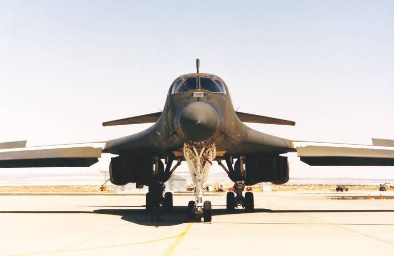 The resurrection of the Rockwell B-1 must rank among the most extraordinary performances of the United States' defence industry. Within specifications, under cost and ahead of schedule, all remarkable achievements given the scale of the programme and the sophistication of the aircraft. The B-1B is easily the most complex airborne weapon system ever to enter production. Differing significantly from its evolutionary predecessor the B-1A, the B-1B is a true muitirole combat aircraft which has been carefully optimised as a precision tool for surgical long-range power projection. As such it offers a credible capability to penetrate Soviet PVO defences. The rate at which the Russians are currently deploying the new MiG-29 Fulcrum, MiG-31 Foxhound and Su-27 Flanker, all equipped with infra-red Search and Track Sets in an attempt to cope with SAC's electronic warfare capability, clearly testifies to the threat the Russians perceive in the B-1B force. Whether these aircraft can cope with the B-1B remains open to debate, TAC's fighters have to date apparently put up a less than convincing performance in hunting the elusive terrain following bomber. It was this aspect of the USAF's Bomber Penetration Evaluation (BPE) that ultimately led to the revival of the B-1 programme, killed off by the Carter Administration at the end of June, 1977. Fortunately enough, sufficient support existed among US legislators at the time to provide funds for continuing research, development, test and evaluation (RDT&E) of the B-1 aircraft after the cancellation of the production order. This saw a series of penetration tests flown at the Nellis range, under the BPE programme. B-1A prototype #3, with a brassboard cross-eye deception jammer fitted, flew a series of sorties against targets covered by ground based radars, AWACS platforms and F-15 fighters. The results were encouraging and in July, 1980, the USAF brought B-1A prototype #4, equipped with the full prototype defensive and offensive avionic systems, into the test programme. By April, 1981, seventy sorties were flown and the results of these offered substantial support for the aircraft's capability. Although SAC's long-term planning envisaged the Stealth / Advanced Technology Bomber (ATB) as the front line long range penetrator at the turn of the century, the loss of 240 B-1As resulted in a major reduction in force capability in the near term. The B-52s could not be considered a credible strike force for hitting key Soviet targets and thus a gap filler was required. Various options were reviewed, including a rather pregnant looking derivative of the FB-111, while lobbyists acting on behalf of many of the 5,300 contractors and suppliers involved in the B-1A programme continued working hard at raising support for reviving the stalled B-1 programme. Amidst these events an Air Force Scientific Advisory Board study identified a future need for far broader capabilities in strategic aircraft and concluded that a derivative of the B-1A would be best suited to near term SAC requirements. Meanwhile the Reagan Administration had pledged to upgrade US strategic forces and the decision was made to provide SAC with 100 new B-1B multi role long-range aircraft. In January 1982 President Ronald Reagan stated that 100 B-1B aircraft could be produced for US$20.5 billion in 1981 dollars, with an Initial Operational Capability (IOC) to be attained in 1986. A US$2.2 billion full scale development and B-1B lot 1 production contract followed shortly. One of the most significant arguments supporting the decision was the maturity of the basic B-1 airframe design, largely frozen by then and the availability of a capable baseline offensive avionic system developed for a B-52 upgrade. Both would contain costs, a view borne out by the subsequent development programme. Rockwell B-1B Long-Range Combat Aircraft The new B-1B was optimised for the split role of a strategic nuclear and long-range conventional bomber. The latter role included maritime reconnaissance/strike, aerial mine laying, anti-submarine patrol and conventional strike in support of theatre operations. The heavy conventional payloads and to electronic means in defence penetration both led SAC to discard top end supersonic performance in order to reduce radar cross section (RCS) and improve payload/range performance. The new aircraft, with 1/10th the RCS of the B-1A (presumably in the J-band so beloved of Soviet SAM designers...), would penetrate at high subsonic speeds several hundred feet above the ground and use its electronic arsenal as its primary penetration aid. This led to the adoption of new engine nacelles with fixed inlets, greatly enhanced offensive and defensive avionics and structural changes to cope with an 82,000 lb increase in maximum gross weight. Significantly, 8,000 lb of empty weight was saved by the use of ejection seats. The new B-1 would carry the AGM-86B cruise missile internally and on external hard points which could also carry other ordnance. The planned reduction in wing sweep angle to simplify the wing glove was later abandoned. To accelerate the development programme, flight tests were carried out on B-1A No2 which received some modifications to bring it closer to B standard. B-1A No4 performed as a test bed for the offensive and defensive avionics, supported later by the first production B-1B. Tragically No2 was lost in an accident in August, 1984 killing Rockwell test pilot Tommie Benefield. The crash was attributed to aircrew error in handling the aircraft at low level with the automatic CG/fuel management system disengaged. The elegant lines of the B-1, certainly one of the most graceful of postwar aircraft, belie its devastating nature. With F-111-like low level penetration capability this aircraft can carry up to 24 2000 lb iron bombs on its three rotary weapon launchers. The initial B-1As and hybrid development Bs carried white livery which has now been replaced by the effective lizard wraparound camouflage for low level operations. The first production B-1B was rolled out on the 4th September, 1984, five months ahead of schedule and first flew in mid October, 1984. SAC received its first aircraft on the 29th June, 1985. Over the next two years 98 aircraft are scheduled to be delivered, 29 to Dyess AFB in Texas, 17 to McConnell AFB in Kansas, 35 to Ellsworth AFB in South Dakota and 17 to Grand Forks AFB in North Dakota. These locations were chosen to maximise the flight time of Soviet SLBMs launched off the coast on shallow trajectories thus discouraging a pre-emptive strike at the B-1 force. The B-1B is a highly capable strike platform which will provide the USAF with significant conventional and nuclear muscle for at least two decades. The sophistication of this aircraft becomes most apparent upon closer examination. The B-1B Airframe The airframe of the B-1B is very close to that of the A-model but incorporates aerodynamic, detail and structural changes to match the revised role and to ease production. The basic structural assemblies of the B-1A are retained with the exception of the crew module which was deleted to save weight and increase crew survivability. The Forward Fuselage is built by Rockwell's North American Aircraft Operations (NAAO) and includes a revised radar/avionic bay and the new crew area. To cut assembly costs the avionic equipment racks and associated cabling in the central avionic bay are fitted into and debugged in the fuselage halves prior to joining. The Forward Intermediate Fuselage section previously containing the forward and intermediate weapon bays experienced numerous structural changes. These resulted from the need to carry the Common Strategic Rotary Launcher (CSRL) with eight ALCMs. The added length forced the removal of the fixed bulkhead between the bays and its replacement with a movable one. The resulting single Forward Weapon Bay required in turn structural changes for launcher attachment points and fuel lines for an optional extra fuel tank. A retractable spoiler was added to the front of the bay to avoid difficulties with the previously troublesome turbulent airflow under the open bays. The new weapon bay is more flexible than its predecessors. Fitted with a pair of rotary launchers fore and one launcher aft the aircraft can carry 24 B-61 or B-83 nuclear devices, or 24 AGM-69 SRAM missiles or 12 B-28 or B-43 nuclear devices. External hardpoints for six dual and two single pylons allow carriage of a further 14 ALCMs or further SRAMs. Flying conventional strikes the aircraft can carry 24 2,000 lb Mk.84 demolition bombs or up to 84 500 lb Mk.82 demolition bombs, placing it in the class of the B-52D. The Aft Intermediate Fuselage and Aft Fuselage are both built by Vought and joined at the Rockwell assembly facility. The wings, built by Avco, retain their integral fuel storage. Skinned above with Alcoa 2124 and below with Alcoa 2219 Aluminium alloys, they are exceptionally stiff to cope with the structural loads induced by terrain following. The inboard wing about the pivots is Titanium alloy with stainless steel bushes inserted (after cooling with liquid nitrogen they expand to achieve a permanent fit). The NAAO built nacelles were an area of major changes. The Automatic Inlet Control System (AICS) of the Mach 2 B-1A was removed together with its sensors and associated doors, ramps and actuators although ram scoops for the air conditioning are still used. Inlet geometry was optimised for low altitude high subsonic cruise with some inlet curvature to conceal the engine fans from radar. This appears to have been successful in spite of the relatively short inlet ducts. The changes in inlet geometry and aircraft mission necessarily resulted in changes to the General Electric F101 powerplants, leading to the new F101-GE-102. Flight tests demonstrated that the low level role was far more punishing than anticipated, with five times the number of thermal cycles expected. The additional wear led to a degradation of engine performance over time which was unacceptable given that the B-1B would spend a lot more time at low level and high gross weights. The new F101-GE-102 differs from the -100 in several respects. The low and high pressure turbine stages employ more durable materials, several forgings have been replaced with cheaper castings and the afterburner stage was redesigned. Fuel flow was redistributed about the spray bars to improve combustion stability in some flight regimes, while the nozzle was changed substantially. The -102 nozzle employs 12 flaps (segments) with six actuators and no flap seals; this arrangement avoids the seal wear out problem of the eight flap -100 nozzle while also saving on two actuators. These changes were a major contribution to bringing mean time between overhauls up to the USAF requirement of 3,000 hrs. Meanwhile other modifications were needed to cope with the serpentine low RCS inlet geometry. The first stage fan blades were altered to increase pumping capacity by 5%, three of the twenty strut frames in front of the fan were removed to increase airflow and the fan vanes were re-staggered to reduce flow distortion at the vane tips. In spite of the number of specific changes to the engine, it still retains 95% commonality with the core of the F-110 derivative fighter engine powering the F-14D, F-15 and F-16. With a 2:1 bypass ratio the -102 delivers 15,000 lbf thrust in military power and 30,000 lbf in reheat though SFC (Specific Fuel Consumption) figures on dry thrust have not been released. The engine can also be changed in less than 30 minutes. B-1B Systems The complexity of the B-1B stems to a great degree from the large number of systems installed. The two major groups are the Offensive and Defensive Avionic Systems, which are complemented by the various services and systems associated with the airframe and support of the mission avionics. The Flight Control System of the B-1B defies brief explanation. Although essentially a conventional Stability Control Augmentation System (SCAS) built with eleven Systron-Donner accelerometer/gyro packages, with one group at the CG and one in the nose, it must cope with the problems of variable geometry and large weight/CG changes. Because the B-1 will pitch its nose up uncontrollably beyond a given AOA (angle of attack), (ie. stall), the SCAS is fitted with a Stall Inhibitor System (SIS) which restricts AOA to avoid entering this unstable mode. However, AOA close to this limit is often required to maintain desired lift at higher gross weights so the SCAS is being fitted with a Stability Enhancement Function (SEF) from aircraft #19. The SEF has been described as providing similar high authority control as the SCAS in the statically unstable F-16A thus enabling the flight envelope to be expanded up to the airframe's high gross weight stability limit. The B-1B's Fuel Center of Gravity Management System has also received some modifications primarily to improve aircrew awareness of CG state so that a repeat of the #2 crash will be avoided. The LARC ride control system is now called the Structural Mode Control System (SMCS) which perhaps better describes its function. It drives the nose vanes and lower rudder segment (see Part 1 Nov AA) to reduce structural loads at low level. Terrain Following (TF) flight is an important part of the B-1B's role enabling it to avoid surface radars and to degrade the performance of lookdown/shootdown radars. The B-1B employs two of its eight IBM AP-101F computers as dedicated redundant TF computers. The AP-101F is a dual instruction set derivative of the earlier and slower AP-101C used for the B-52 offensive avionic upgrade. The F-model runs at about 1 MIPS (million of instructions/sec) and is micro coded either to a proprietary instruction set or MIL-STD-1750. Most of the software running on the eight AP-101Fs is written in Jovial J3B, it is very likely that much of it was derived from that written for the B-52 avionic upgrade. The TF computers interface with the SCAS via a pair of Boeing Signal Data Converters which would provide analogue/digital, digital/analogue and timing conversion functions. The aircraft's eight computers are split into four groups; four form the core of the offensive avionics, two perform as TF computers, one as the defensive avionics supervisory processor and the last unit serves as the Central Integrated Test System's (CITS) central computer. These processors are tied into four dual redundant MIL-STD-1553B serial data busses which connect to almost all on board systems, they are also supported by an IBM nonvolatile Core Mass Storage Device and a pair of Sundstrand Data Transfer Units. Both of these would be used for targeting cruise missiles. The CITS system is of great importance, it monitors the operational status of all other subsystems and reports any battle damage or malfunctions detected. The Boeing ASQ-184 Offensive Weapon Control System The Boeing Offensive Avionic System (OAS) integrates all navigation and attack functions. It was developed from an upgrade package designed for the B-52G/H force and is built around four AP-101F computers, termed Avionic Computer Control (ACC) units. One ACC provides Nav functions, one Task Display and Control, one Weapon Management (see AA Sept 85 p73) with the last ACC serving as a monitor and backup unit. These four ACCs are supplemented by the pair of TF computers. The OAS receives inputs from a number of sensors. A pair of Honeywell APN-224 Low Altitude Radar Altimeters (LARA) provide high rate altitude measurements for terrain following, while a Teledyne APN-218 Doppler set provides precise velocity measurement in all axis to supplement the inertial systems. The primary navigation reference is a pair of Singer Kearfott SKN 2440 Inertial Navigation Units (INU). The OAS is supervised by the Offensive Systems Operator (OSO) who sits at the starboard aft station. He will use two Multi Function Displays (MFD) and a radar display all of which are tied into the data busses. From this station the OSO will navigate and acquire/attack targets. Display and system control is implemented with multi function keyboards and a Tracking Control Handle, a facility to upload mission particulars with a magnetic tape cartridge is also apparently available. SAC will eventually operate 100 B-1Bs at a high state of mission readiness. In conceptual terms the nearest Soviet equivalent is the well known Tupolev Tu-22M Backfire though this aircraft is used primarily in the maritime strike role. The first SAC 8-1 B wing became operational during 1986 while current production rate has now reached its peak of 4 a month against an April 1988 target for delivery of the final aircraft. The Westinghouse APQ-164 Offensive Radar System The ORS is the primary attack sensor in the B-1B and fulfils several key functions, including terrain following. The 164 was developed out of the EAR (electronically agile radar) programme of the late seventies which aimed at exploiting phased array technology in a tactical radar, it is unique in that it combines both attack radar and terrain following radar functions in a single antenna two channel unit. The extremely difficult requirement for a TF/attack radar which could offer a 99% probability of survival over 15 hours of operation led to the adoption of a two channel architecture, which follows through from the receivers up to the independent TF ACCs (computers). At any instant one channel is active while the other is in hot standby, the only element in the radar common to both channels is the actual phased array antenna. To reduce costs and improve reliability Westinghouse designed the 164 about several LRUs (black boxes) used in the mature APG-68 F-16 radar, itself most reliable with a 120hr class MTBF. The ORS offers 19 operating modes and time-shared use between the pilots and OSO (thus offering the illusion of an independent radar for each). This versatility is a result of two design features, the use of programmable signal processors and the use of an electronically controlled phased array antenna. The unique honeycomb appearance of the antenna is due to the 1526 miniature phase shifter modules, each of which is an independent receive/transmit element. By electronically manipulating the microwave signal phase lead/lag of these elements the radar can shape and point its beam, within certain limits, almost instantaneously. While this technique allows concurrent TF/attack modes it also offers lower radar cross section than a conventional antenna and graceful degradation rather than catastrophic failure as individual elements fail. In TF mode the ORS scans terrain up to 10nm ahead of the aircraft and stores a height vs distance profile. Scan rates depend on which of the 11 clearance altitudes are set and upon velocity and terrain. Only a narrow corridor is covered to minimise detectable emissions. Terrain Avoidance mode assists penetration by displaying only terrain features above a set altitude while Velocity Update mode emulates a Doppler nav set. A Weather mode is available offering circular beam polarization. Several attack modes may be used. Real Beam Groundmap and Synthetic Aperture Radar mode offer coarse and high resolution mapping for attack and INS updating, while a side looking Strip Mapping mode is available for standoff attacks. Moving Target Indicator and Moving Target Track modes are offered including overlay presentation, these are essentially tactical strike modes. A unique mode offered by the 164 is High Altitude Calibrate in which the antenna is tilted down and the beam fired vertically down to obtain precise altitude supplementing the LARA and barometric altimeter when bombing. The high reliability of the APQ-164 and its flexibility offer a lot of system level redundancy which reduces the aircraft's sensitivity to failures in other OAS sensors; this should substantially reduce instances of mission aborts. Coupled with the use of standoff munitions the OAS provides the B-1B with the ability to accurately hit point targets deep inside hostile territory. To survive in this environment the aircraft must exploit both its low radar cross section and defensive avionics. The Eaton-AIL ALQ-161 Radio Frequency Surveillance/Electronic Counter Measures System The vast ALQ-161 is the most complex defensive jamming system ever installed in a combat aircraft. Built up of 107 LRUs of 52 different types weighing in at 5,2001b the 161 represents a major exercise in system engineering. It is unique in that it is the first system to provide complete integration of RHAW (radar warning) and jamming functions in a single system - a feature which greatly improves utilization of jamming resources available. The 161 divides the world outside the B-1B into three 120 degree segments each covered by one of its three antenna bays; one in each glove fairing and one in the tail cone. The receivers, transmitters and antennas in these bays tie into the remainder of the 161 via six redundant MIL-STD-1553B data busses. Control is exercised, via Jam Logic units, by the 161's Defensive Management Subsystem (DMS) AP-101 F ACC which also provides an interface between the 161 and the Defensive Systems Operator (DSO). The DSO occupies the port aft station and monitors the threat situation through two Electronic Display Units and a Multi Function Display. Although the system is highly automated the DSO may intervene thus vastly increasing flexibility (there is no substitute for a devious mind...). The 161 relies on sets of directional receivers, each for particular bands, to detect hostile radar emissions impinging on the aircraft. These are analyzed and, after encoding and data filtering, passed onto the DMS computer for threat assessment and display. The receivers and programmable jammers are under the direct control of two Jamming Allocation Logic Units, dubbed 'Jam Logic A and B' boxes which via the 1553 busses communicate with the electronically steerable antennas and programmable transmitters. The AIL designed solid state low band transmitters and Northrop Travelling Wave Tube high band transmitters feed via wave guides into a strip line network which feeds the multiple phase elements in the steerable Sedco antenna arrays (which use a technique similar to that in the radar to achieve near instant beam pointing). The jam logic will coordinate beam pointing and jammer transmissions to hit each victim radar when it is most vulnerable (eg into its antenna side lobes), the system's ability to time share and allocate priority enables it to cope with multiple threats most effectively. Much of the computing horsepower used in analyzing threat signals and computing jamming wave forms is provided by a set of dedicated microprogrammable high speed Litton LC-4561D computers, which thus allow the DMS computer to efficiently perform in its dedicated management role. Packaging the immense 161 appears to have been a problem, as much of the low band hardware and power supplies have been buried deep in the aft fuselage and main wheel well. The jam logic and DMS ACC reside in the central avionic bay racks. Some sources indicate that difficulties with the 161's tail warning radar subsystem have led to its replacement with the ALQ- 153 although this was not confirmed at the time of writing. Although SAC are understandably reluctant about describing what the 161 can do, it appears that it will cover bands up to and including the I/J band thus enabling it to defeat newer Soviet SAMs such as the RIM-66A Standard look alike SA-11 Gadfly and the new lookdown/shootdown air intercept radars carried by the Foxhound and Flanker. Techniques for monopulse radar deception jamming are almost certainly implemented. Penetrating hostile airspace the B-1B will rely primarily
upon
low altitude, its low radar cross-section and radar warning receivers
to
avoid detection by threats. If the aircraft must close to a range where
a threat can detect it, for instance through local geography or while
hitting a target; it would then unleash its arsenal of jammers to
confuse its opponents. Although lookdown/shootdown fighters represent
the most effective counter to this aircraft one cannot lose sight of
the
fact that any interceptor (having actually managed to find it)
attempting to kill it must contend with the difficulties of a lookdown
attack and the considerable jamming power output of the ALQ-161.
Infra-red Search & Track Sets may be of use under some
circumstances
but are hampered severely by atmospheric water vapour and background
infra-red emissions (ie. clutter). Given the vast area to be covered by
the Russian Voyska PVO and the quality of much of their equipment and
aircrew it is reasonable to assume that in the foreseeable future the
B-1B will defeat their defensive system.
The B-1B is an awesome combat aircraft with a broad range of both nuclear and conventional capabilities. Hopefully it will never by called upon to demonstrate what it can do. It is, after all, very much a Doomsday Machine.
Part
III
Stealth
On the 11th July, 1986, in the early hours of the morning a USAF fighter aircraft crashed into a hillside in mountainous country, north-east of Bakersfield in Southern California. The pilot, USAF Major Ross Mulhare of the 4450th Tactical Air Group at Nellis AFB, was killed. While fire-fighters battled the resulting bush fire, the USAF declared the crash site a national security area, cordoned it off and subsequently had fire-fighters and other civilians involved sign forms in which they agreed not to disclose what they saw. The consensus of most informed observers in the US was that the aircraft was a Lockheed built Stealth fighter, a strike/recce aircraft designed to penetrate hostile airspace without detection. The USAF's response underscores the military significance of Stealth, a very general term applied to the reduction of a combat aircraft's infra-red, electromagnetic, acoustic and visual signatures and radar cross-section. The objective of Stealth technologies is to deny hostile weapon systems critical target information thus defeating detection, acquisition, tracking and guidance systems. This will reduce the ability of an air defence system to inflict losses, thus increasing the cost effectiveness of tactical and strategic air strikes. This in turn forces an opponent to concentrate a maximum of effort into air defence thus consuming resources otherwise applied to the tactical air battle. The importance of Stealth in the tactical scenario of the late eighties cannot be understated. The Russians are finally closing the technology gap with the mass deployment of the lookdown/shootdown capable MiG-29 Fulcrum and Su-27 Flanker, both serious threats to Allied tactical aircraft. While Russian SAMs did not perform well either in the Bekaa Valley air battles of 1982 or the Libyan air strikes of 1986, the USSR has confronted its difficulties with a proven strategy of vastly increasing concentration. Supplementing existing assets with deployments of the SA-10 Grumble, SA-11 Gadfly and new SA-13 Gopher is alarming as types such as the SA-11 which now carry illuminators on each vehicle and more rounds per vehicle. While successfully jamming larger numbers of newer radars is difficult, the increased number of rounds salvoed by these systems per engagement must increase their overall kill probability. As NATO doesn't possess the depth of expendable buffer territory which the Russians have, it relies heavily on Tacair and cannot withstand sustained high loss rates. The option of deploying newer and more capable jamming equipment has penalties. Because it is threat specific it must be constantly updated, which adds to the high purchase price. Because of its complexity aircraft reliability suffers and large spares stocks must be kept to allow field deployments, which adds to manpower and hardware costs. To successfully jam multiple threats the system must be complex, which inflicts weight penalties. While Anti Radiation Missiles (ARMs) are most effective, they are costly and eat into payload, most noticeably in small tactical aircraft. At some point the cost of these systems becomes unmanageable and other means must be sought. Stealth is an option which offers gains in
availability/dollar
while coping with a broad spectrum of threats. The following will
illustrate this quite clearly.
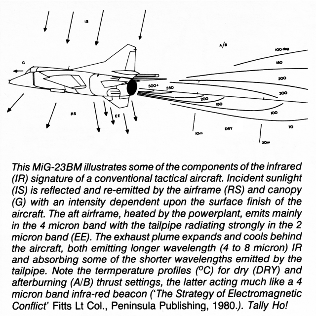
The Infra-Red Signature of an Aircraft Infra-red (IR) radiation is associated with heat. All aircraft radiate IR, some is reflected and reradiated sunlight while the dominant source of IR is the powerplant. Jet engines release large amounts of waste heat, most of which is concentrated in the exhaust plume and hot end of the engine, while some is also conducted through the airframe. Engine IR emissions fall into two areas, the tailpipe and the nozzle. On dry thrust the tailpipe will directly radiate intense IR (modelled as Lambertian source - Auth.) due to a turbine Exhaust Gas Temperature (EGT) of about 1000d degrees C in turbojets and 1300d degrees C in newer turbofan cores. This radiation is most intense when viewed from inside a solid angle (cone) centred on the engine's axis. Once the depth of the tailpipe is out of the Field-Of-View (FOV) of the observer, most of the emissions are confined to the outside of the nozzle which heats to hundreds of degrees Centigrade and the exhaust plume. Airframe heating occurs through conduction of engine heat through structure and the dumping of waste heat from internal systems and avionics. Skin friction can also be significant at high speeds. The magnificent Lockheed SR-71A was designed with strong emphasis on minimum radar cross-section. This was achieved by careful shaping, wing / body blending and the selective application of radar absorbent materials. Infra-Red Signature Suppression As combat aircraft require high agility, the need for increased thrust makes it impossible to substantially reduce their heat output. However measures can be taken to reduce detectability. One technique is to IR emissions into those wavelength bands where atmospheric carbon dioxide and water vapour rapidly absorb IR, which results in a major reduction of the distance at which an IR source such as a tailpipe can be detected. To implement this, avoiding afterburners is a good first step. Ideally, all waste heat from systems would then be dumped into the exhaust flow, which itself would be mixed with cool air before leaving the exhaust nozzle. Cooling the exhaust is useful as it reduces the temperature of the plume and heating of the nozzle and rear fuselage structure, but understandably this has major implications for powerplant efficiency and performance, these are more apparent at a system level. While radiation from the structure and plume can be suppressed straightforwardly, concealing direct radiation from the depth of the tailpipe/turbine has penalties in weight and complexity. Fortunately other measures exist to reduce the prob ability of detection. Rectangular exhaust nozzles may be used to reshape the lobe of the exhaust radiation pattern (the shape of the volume of space behind the exhaust with some nominal IR emission intensity level), squeezing the ellipsoidal pattern of a circular nozzle into a flattish beaver tail shape. To detect the emissions a threat must be astern and at a close altitude, while the range of altitudes over which detection can be made does widen with increasing distance, the intensity of the IR emissions drops rapidly with distance and this hampers detection. This strategy (incidentally used on the A-10A) makes it difficult for a ground based IR Search & Track system to track the tailpipe emissions while also forcing interceptors to approach at the same altitude from astern to get a good IR missile lock. Furthermore, unless the threat aircraft is dead astern, a sharp defensive turn will the tail pipe radiation pattern lobe out of the plane of the threat and may break lock. Another variation on this topic is the use of horizontal louvres in the nozzle. Louvres will further flatten the radiation pattern (for the technically minded the ratio of louvre depth to louvre spacing must be greater than the ratio of nozzle plane of emission depth to nozzle height) but may require cooling and this must be balanced against the gain offered. Other than such active measures, paints with low IR reflectance will usefully reduce the effect of sunlight illuminating the airframe. Electromagnetic Emissions Electromagnetic emissions other than IR, such as radar, IFF, radar altimeters, Doppler nav and communication systems can and will betray the bearing, identity and often intent of a penetrating aircraft. Suppression of this class of emissions is easy to implement in comparison with infra-red. Conceptually it means using passive sensors and not transmitting anything. If transmission is required, then Low Probability of Intercept (LPI) techniques must be applied. These fall into several categories. One aspect of LPI is to carefully manage transmitter power to limit detection range. Another aspect of LPI is the use of very short wavelengths and tight beam transmission to reduce the volume of space where the transmission may be detected. A very powerful technique is pseudo-noise coding which makes transmissions appear like random electrical noise. In this context classical penetration aids such as Terrain Following Radar can be a problem, as a penetrator climbs over a hilltop sweeping its TFR beam up and down it advertises itself for many miles. Jammers can also cause problems, while the victim radar may be deceived a separate listening device will not and may identify the aircraft and its position. While the above emissions are the most significant, electrical noise and interference from an aircraft's onboard systems could conceivably cause difficulties, particularly in a non-metallic airframe. Computers and digital electronics in general generate a lot of interference, therefore careful screening and the use of optical fibres for data transmission between subsystems may become necessary. Radar Cross-Section Radar Cross-Section (RCS) is a measure of the power returned in a radar echo relative to the power impinging on the illuminated target. RCS depends strongly upon the wavelength (which decreases with increasing frequency) of the radar and also upon the shape and skin material used on the target. The dependence of RCS upon frequency is considerable and a cause of grief to radar designers and vehicle designers alike. Where the wavelength is much greater than the target the return is essentially proportional to the size of the target, the effect is called Rayleigh scattering. For this reason Over the Horizon (OTH) radars such as Jindalee are substantially immune to RCS reduction techniques. Increasing the frequency of the radar to the region where its wavelength is comparable in size to the target, the return becomes extremely sensitive to aspect and, will fluctuate dramatically with small changes in viewing angle. This region is termed the resonance region. Beyond this point, as the wavelength becomes smaller than the target, the sensitivity to aspect falls off. This is designated as the optics region. The dependence of RCS upon shape is also significant, while the above applies. The best radar reflectors are trihedral corners, dihedral corners between flat surfaces or flat surfaces and cylinders and flat surfaces themselves. All of these shapes are common on modern aircraft and all exhibit an increasing RCS with frequency (proportional to f^2). Cylindrical and spherical shapes are lesser but significant reflectors, while straight edges are somewhat weaker reflectors. Nevertheless straight edges are a known cause of strong reflections from many supersonic aircraft. The weakest reflectors are curved edges and gentle curves on flattish surfaces, most of which become weaker with increasing frequency. It is for these reasons that modern combat aircraft, essentially composite shapes, exhibit such a great variation of RCS with wavelength and aspect. Other major contributors to an aircraft's RCS must be considered though. Holes, inlets, scoops, bays and, in particular, cockpits and radar/ECM bays, radar transparent canopies or radomes, are all significant reflectors. External stores fall into the same category. All of these may reflect strongly and from some aspects even dominate the RCS. Engine inlets and tailpipes are an extreme instance of this category, reflecting but also often allowing incoming waves to impinge on rotating fan/compressors or turbines. These reflect an echo which is modulated often well enough to identify the type of engine (an early bug with the F-15A's APG-63 radar set was its sensitivity to this effect, jet engine modulation, which resulted in multiple target images. Newer radars use it for target recognition). Another interesting aspect of RCS is the surface (travelling) wave effect, where a wave impinging on a flattish surface, eg. wing, from a shallow angle travels along it until it hits a discontinuity, eg. control surface or leading/trailing edge, from which it bounces off possibly in the direction of the illuminating radar. In general, any aircraft can be seen as a large group of individual radar reflectors, each of which represents some facet of the aircraft's shape or detail features and all of which depend in size upon the aspect of the aircraft and the wavelength of the illuminating radar. RCS Reduction RCS reduction is not a trivial task and is certainly not practical for existing designs. Of the strategies available in designing a new aircraft, the simplest is to identify and eliminate flare spots, individual contributors to the RCS, placing emphasis on those aspects and radar wavelengths relevant to the mission profile. For most combat aircraft frontal and to some degree aft aspects are most important as these are presented to a threat with a relatively low line of sight (LOS) angular rate during attack and egress. This will quickly lead designers to smooth, flattish airframes with nose chines and wing/body blending to remove all corners and as many edges as possible. Inlets will be on the top of the airframe to shield them from ground based radar. This strategy will suppress echoes from major airframe features but as these are reduced, the RCS of other features will become dominant. The next phase involves conductive plating (eg. gold as on EA-6B) of the canopy, fitting tuned (wavelength selective) radomes/panels over the radar bay (if used) and using shared apertures for the Radar Homing And Warning (RHAW) and jammers, while ensuring that these do not reflect at wavelengths outside of their range of use. Engine inlets acquire S-bends or even baffles to conceal the compressor face. Airflow/pressure sensors are redesigned for low RCS. Rivets/fasteners and latches must be very flush and of materials with similar electrical behaviour to the skin. Panel edges, control surfaces, flaps and bay door edges must fit tightly and must not expose edges under load or use. The next phase involves the application of Radar Absorbent Materials (RAM) and Radar Absorbent Structure (RAS). RAM and RAS will absorb an impinging electromagnetic wave and dissipate it as heat. The ideal RAM/RAS would be indistinguishable from free space to an impinging wave of any wavelength, which would be absorbed completely without any reflection. Real world RAM/RAS tends to approach the ideal only in a narrow frequency band and often must be inches thick to be effective. RAM/RAS is a very broad subject, the two basic categories are broadband and resonant, the latter absorbent to some narrow band of frequencies. There are several families of RAM; dielectric absorbers such as Jaumann absorbers and graded dielectric RAM, magnetic RAM such as carbonyl iron or ferrites and the newer circuit analogue (CA) RAM, which is made of multiple layers or dielectric (eg. plastic) material with geometrical patterns (eg. Jerusalem crosses) of electrically conductive material deposited on them. Each family of RAM has its strengths, magnetic RAM at lower frequencies, dielectric RAM in the upper bands. An area where the Americans have made progress (and kept most of it well classified) is hybrid RAM combining layers of several types of RAM to minimise reflection over as wide a frequency band as possible. These materials often fall into the class of RAS, which is highly desirable as most RAM has appalling mechanical properties particularly for airframe design. Good structural materials such as Aluminium are excellent radar reflectors, even carbon fibre and boron epoxy can be fairly reflective. A typical RAS would be a honeycomb using CA RAM sheets for high band absorption and magnetic RAM for lower bands. Some measure of RAM performance may be gained from a description of a graded dielectric RAM in Radar Cross-Section (Knott EF, Artech House, 1985) which displayed roughly sixtyfold attenuation of an impinging wave (compared to zero for a reflec tor) in the I-band which peaked at better than thousandfold attenuation in the middle of the J-band. (Above and below) The MiG-29 Fulcrum A demonstrates Soviet contempt for Western radar and missile design. The large inlets, long fuselage tunnel, profusion of corners, absence of vertical stabiliser cant, vertical stabiliser / fences and inlet louvres all make significant contributions to its radar cross-section. The smoke trails of the R-33D powerplants also assist in visual detection of this aircraft.
Note: many radar systems offer selectable frequencies which may overlap band boundaries. In general the E/F bands are used for surveillance/acquisition and AEW and the I/J bands for AI and tracking/illumination for missile guidance. Types listed are only typical and not exhaustive - Author.
The RAM designer relies heavily on computer aided design techniques to model the performance of his material and tailor it to a mission. Airframe RCS analysis as a whole relies heavily on software/computer modelling, Northrop's GENSCAT, MISCAT and HELISCAT being typical tools for the job. The designer of a Stealth aircraft has therefore a broad range of options available. RCS Reduction and Defence Penetration Radar based air defence systems such as Russia's PVO employ a broad range of radar and weapon systems. Most long range surveillance radars operate in the lower bands, while SAM acquisition and guidance radars tend to the G, H, I and J-bands with SAM/AAM seekers and AI radars in the I/J-bands (smaller antenna size constraint). While reducing RCS will in general reduce detection and tracking range, important tradeoffs must be made between aerodynamic performance, RCS in the given bands and jammer capability for any given scenario. A typical PVO response to a penetrator, for instance, would initially involve detection by long-range low band radar. Such systems are seldom accurate, therefore an interceptor is despatched into the immediate area to acquire the target on its Airborne Intercept (AI) radar and carry out an attack with AAMs. If this fails the penetrator will have to pass through a SAM umbrella before and often over the target area, the SAM acquisition radars would be alerted to the approaching aircraft. If an Airborne Early Warning platform is involved it would support interceptors and possibly SAMs by data linking target information acquired with its radar, probably operating in the E/F bands. To evade detection the penetrator must therefore defeat radars covering virtually all bands while to evade terminal threats it must defeat radars predominantly in the upper bands. Two aspects of defeating these radars must be considered, detection range and burnthrough. Detection range of a target is proportional to the fourth root of target RCS. Therefore a tenfold reduction in RCS reduces detection range to about 56%, a hundredfold reduction of RCS reduces detection range to about 32%, a thousandfold reduction to about 18% and so on... While this isn't a dramatic gain it must be pointed out that the volume of airspace covered by a radar is proportional to (within limits) the cube of detection range, therefore 56% of detection range translates to about 18% of the original volume of airspace [Editor's Note 2005: at greater distances a square law dependency in a more relevatn model]. Burnthrough range is the distance at which a radar can successfully detect a target which has been jamming it, at this point the echo has become sufficiently stronger than the jammer's emissions. What is most significant is that burnthrough range is proportional to the square root of target RCS. Therefore a tenfold reduction in RCS reduces burnthrough range to about 32%, a hundredfold reduction to 10%, a thousandfold reduction to about 3.2% and so on... A penetrator with a hundredfold reduced frontal RCS compared to a conventional aircraft approaching a radar will be detected at about one third of the range and will be able to successfully jam, assuming the same jammer, over 9/10 of the distance over which a conventional aircraft could be successfully tracked. This becomes understandably significant. The designer of a stealthy penetrator must weigh the importance of the various threat systems against the cost of his design. Low band (eg. UHF) radars can be defeated relatively cheaply by terrain masking when surface based, if these are carried on an AEW aircraft the size limit of the antenna rotodome will almost certainly result in large antenna sidelobes which ease jamming while this family of systems is not renowned for spectacular lookdown performance. Higher bands such as G/H and particularly I/J are associated with threats such as fighters and SAMs and therefore RCS reduction offers a large payoff. This is enhanced by the dependence of most IR guided weapons upon radar for target acquisition and tracking, defeating the fire control system will often prevent a successful launch of an IR SAM or AAM. Ideally a stealthy penetrator would employ standoff fire & forget weapons with a range greater than or equal to the detection range by the target's defences, or at least the burnthrough range. The former instance offers the advantage of surprise if the weapon is not detected. Combining these two families of systems defeats the air defence system as it cannot inflict any attrition by means other than chance. Given the high cost per airframe of stealthy aircraft the highest payoff is in reconnaissance/electronic reconnaissance, defence suppression and strikes on high value heavily defended targets. A very useful application is the use of stealthy aircraft to clear corridors through SAM belts allowing conventional aircraft to pour through. A Stealthy Tactical Fighter The high payoff in using stealthy aircraft for the strike/recce family of roles reflects in the USAF's CSIRS Stealth fighter programme and the USN's ATA strike aircraft programme being the first operational stealth aircraft to be deployed or planned for deployment by these services. This class of mission would typically involve penetrating hostile battlefield and static defences up to several hundred nautical miles deep, preferably while not being detected. It is not difficult to envisage a 25,000 lb empty weight class aircraft with two low bypass ratio fans and internal capacity for 2,000 to 4,000 lb of disposable payload (ie. a Mk.84 2000 lb laser guided bomb fits roughly into a 2'x2'x16' volume folded). The choice of powerplant would be interesting, while a turbofan has better specific fuel consumption (SFC) and a cooler exhaust plume than a turbojet, its thrust falls off more quickly at higher speeds and reheat is thus required. Afterburning is to be avoided in a stealthy design, while afterburners also add about 30% to the mass of an engine. Fans also tend to larger diameters which make them more difficult to package into a low profile design. For an acceptable combat thrust/weight ratio, given about 10,000 to 12,000 lb internal fuel, the aircraft would require about 15,000 lb of thrust in military (dry) power. The airframe would almost certainly employ a double delta planform (cf the F-16F), with chines and extensive wing/body blending. The choice of curved or straight chine and wing leading/trailing edges will depend on the designers' preference for strong glint (echoes) in some directions versus weaker glint over a broader range of angles and of course aerodynamic performance. Vertical stabilizers if used would be canted inward with rounding of edges subject to the above tradeoff. The crew, presumably a pilot and Electronic Warfare Officer/Weapon Systems Officer, would sit in tandem as this layout blends into the forward fuselage geometry more easily and offers more instrument panel area per frontal fuselage cross-section. The powerplants could be blended into the wing (cf SR-71/YF-12) or clustered in the aft fuselage, subject to weapon bay placement. This decision would depend upon many tradeoffs in drag, quality of inlet airflow vs AoA and frontal RCS. The engines would employ rectangular nozzles, possibly with louvres, cooling air being drawn from the inlet flow. Most of the airframe structure would employ carbon fibre particularly to offset the weight penalty of using hybrid RAS skins, doors, panels and RAM in non-structural areas. All fuel would be carried in the wing/body volume. A digital active fly-by wire flight control system would be used to provide both accept able handling and enveloped limiting to offset the penalties arising from the above tradeoffs, particularly AoA restrictions and yaw/pitch stability. The aircraft would carry a sophisticated RHAW and recorder in the class of the APR-38/45 (cf F-4G Wild Weasel) which would be a critical tool in most of its roles. A navigation Flir and raster scan wide angle HUD system (cf F-16/F-15E Lantirn), complemented with narrow FOV Flir and Low Light Television would be useful, together with a long-range TV telescope such as TISEO. A facility to slave the optical sensors' LOS to RHAW designated targets would also be a desirable feature for recce and electronic recce, thus alleviating one of the classical problems in electronic intelligence gathering (ie. what signal belongs to what device). For precision strike, standoff weapons such as SLAM (land attack Harpoon) and an IR Maverick derivative would be used, for defence suppression Maverick and ARMs would be carried. A self defensive weapon could be a later AMRAAM with passive anti-radiation homing and home-on-jam modes. All weapons would be carried internally and ejected very quickly to minimise bay open time. Flying mainly night missions an overall dark low IR
reflectance paint would be used. The aircraft would ideally be
optimised
for a medium to low level high subsonic mission profile, taking
advantage of terrain if and when appropriate.
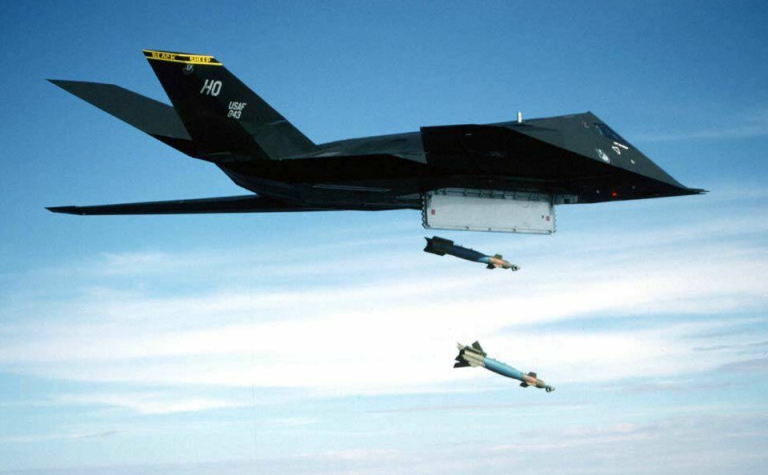
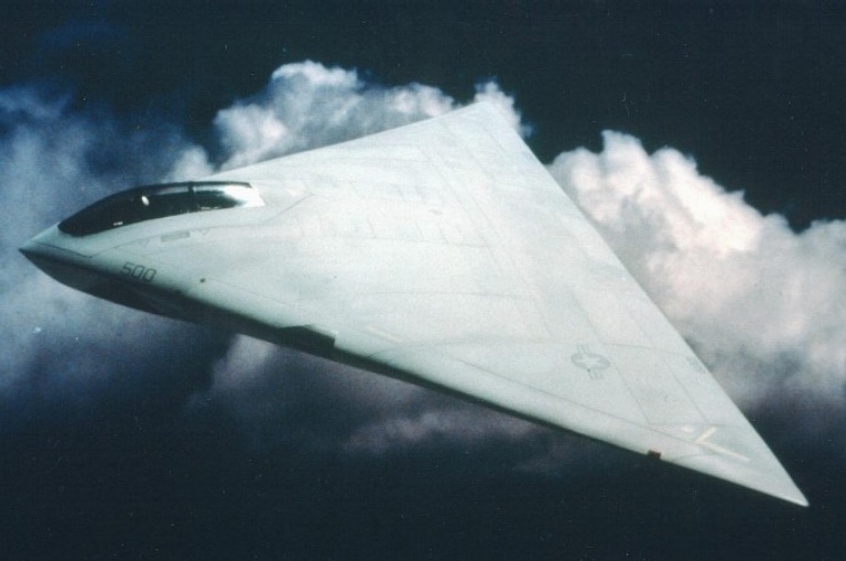
The USAF CSIRS Stealth Fighter The Covert Survivable In Weather Reconnaissance/Strike fighter is a 'black' programme and has never been officially acknowledged, therefore of what is published in the open literature, much is in conjecture and some may be US DoD disinformation. A reasonable amount of what has been published in credible and amounts to the following. In 1973 the USAF and DARPA initiated the Have Blue programme aimed at low observable technology and by the end of the year issued an RFP for the experimental Stealth Tactical (XST) technology demonstrator. The XST was characterised by low frontal and beam RCS, the use of RAM and cooled low IR exhausts. In 1976 Lockheed won the contract for five prototypes. The Lockheed XST first flew in 1977, a 35ft subsonic airframe with two unreheated J-85 turbojets. The aircraft has been reported as having a double delta planform with chines and wing/body blending much like the SR-71. Although two prototypes crashed, tests were successful and led to a 1981 contract for the full scale CSIRS, often incorrectly designated the F-19A. The CSIRS itself first flew in 1982 and is reported to be
sized much like an F-18, 55ft long with 35ft span and a gross weight of
around 30,000 lb. Several sources have reported the aircraft as being
powered by a pair of modified GE F404 turbofans developing about 12,000
lb of thrust each. A Lear Siegler digital flight control system was
attributed by one source. Most of the aircraft's structure has been
described as composite, using carbon fibre and boron epoxy composite.
Extensive use is apparently made of RAM, particularly magnetic
absorbers. Most sources agree that the aircraft is tasked with defence
suppression and recce.
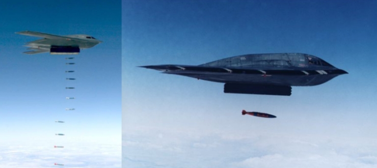
The USAF ATB Stealth Bomber The existence of the Advanced Technology Bomber is somewhat less a matter of conjecture, thanks to the indiscretion of the Carter Administration under fire over the B-1 cancellation. On the other hand less information is available on the programme, though this may reflect its lesser maturity. RFPs for the ATB were issued in 1981, with a Northrop/Boeing team winning a full scale development programme contract with a long-term outlook for 132 aircraft in a US$30 billion programme. Most sources agree that the aircraft is a flying wing powered by four modified GE F-101 fans, some suggest the designation B-2A. Gross weight is reported about 400,000 lb, with a maximum 40,000 lb weapon load, carried internally. The Common Strategic Rotary Launcher has been designated for use in the ATB and a secure plant at Pico Rivera, near Los Angeles, has been set up by Northrop for work on the programme. On the basis of Northrop's known involvement in ECM systems, RCS analysis and flying wing design and Boeing's well proven track record in long-range bomber design and offensive and defensive avionic management systems design, this is quite credible. The ATB will almost certainly penetrate at high subsonic
speeds and medium altitudes, using cloud cover to foil detection by
thermal imaging satellites (cf Teal Ruby) and ground based sensors. If
threats such as OTH radar are encountered, it may descend to low level
and exploit clutter and ECM to defeat the threat. Targets will be
attacked mainly with standoff weapons such as the stealthy Advanced
Cruise Missile (ACM), currently in development. The ATB will certainly
exploit extensive RAS, RAM and most of its vitals will be buried deep
inside.
JTACMS and ATA While the CSIRS, ATB and ACM have attracted most of the attention, two other major stealth programmes no less significant are under way. One of these is the USAF/Army Joint Tactical Cruise Missile System (JTACMS) which is a stealthy precision deep strike weapon for hitting battlefield and follow-on forces. JTACMS is heavily classified, though we believe it is expected to be able to deliver a wide range of munitions. Interestingly it is an outgrowth of a Northrop proposal, the NV-150 with a Williams fan engine, satellite/ring laser gyro nav and composite airframe (see TE Sept 84 AA p54), which displaced the contending ballistic T-16 and T-22 weapons. The second programme is the USN's Advanced Tactical Aircraft (ATA), a projected stealth technology all weather deep strike replacement for the A-6F Intruder. This programme is also classified, but given current USN thinking almost certainly a high subsonic 55,000 Ib gross weight class aircraft with a 1000+ nm unrefuelled strike radius. A derivative of the GE F404 turbofan has been selected for the aircraft. The ATA programme is currently in the demonstration/validation phase, with Grumman/Northrop and McDonnell Douglas/General Dynamics developing competing designs for the full scale development programme. Significantly in mid 1986 the US DoD directed the USAF to consider adapting the ATA to fulfil the role of an F-111 /F-15E replacement with an IOC in the late nineties. Over the last half decade stealth technology has transitioned from a development concept to a credible tool for projection of tactical and strategic air power. It promises significant gains in survivability and combat effectiveness which may well offset the additional acquisition costs. Given the reluctance of Australian governments to make a
long-term commitment to supporting the F-111 strike force, one cannot
help but think of what options would be sought to supplant this
aircraft. In the longer term Stealth may be the only option. |
|||
|
|||||||||||||
|
|
|
|
|
|
|
|
||||||
|
|
|
|
|
|
|
|
||||||
|
|||||||||||||
| Artwork, graphic design, layout and text © 2004 - 2014 Carlo Kopp; Text © 2004 - 2014 Peter Goon; All rights reserved. Recommended browsers. Contact webmaster. Site navigation hints. Current hot topics. | |||||||||||||
|
Site Update
Status:
$Revision: 1.753 $
Site History: Notices
and
Updates / NLA Pandora Archive
|
|||||||||||||
|
|
Tweet | Follow @APA_Updates | |||||||||||
|
|
|||||||||||||
|
|
|||||||||||||