|
||||||||||||||||||||||
 |
||||||||||||||||||||||
 |
 |
 |
 |
 |
 |
 |
 |
|||||||||||||||
 |
 |
 |

|
 |
 |
 |
 |
|||||||||||||||
 [Click for more ...]") |
||||||||||||||||||||||
| Last Updated: Mon Jan 27 11:18:09 UTC 2014 | ||||||||||||||||||||||
|
||||||||||||||||||||||
|
||||||||||||||||||||||
|
||||||||||||||||||||||
|
|
|
|
|
|
|
|
|||||||||||||||
|
|
|
|
|
|
|
|
|||||||||||||||
|
||||||||||||||||||||||
| Last Updated: Mon Jan 27 11:18:09 UTC 2014 | ||||||||||||||||||||||
|
||||||||||||||||||||||
| AEW&C
- Phased Array Technology Parts 1 & 2 |
|||
|
|||
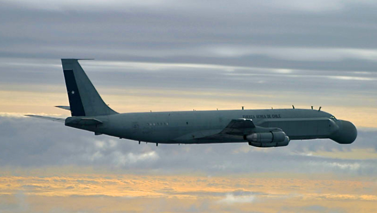 IAI Condor AEW&C system
equipped with the early Elta IAI EL/M-2075 Phalcon AESA (Chilean AF).
|
|||
|
The technology of Airborne Early Warning (AEW&C) systems is at a generational junction point at this time. We are now witnessing the next step in the lengthy evolution of this key technology, that being the transition from mechanically scanned antenna technology to electronically scanned phased array technology. Phased array antenna technology has been in use for some decades, but most applications have been confined to ground based systems, due significant weight and size penalties associated with older families of electronic devices. The ongoing march of miniaturisation combined with significant improvements in microwave power transistor device technology has now allowed its wider use in airborne applications. Conventional Antenna Systems The purpose of a radar antenna is to focus a beam of electromagnetic energy into a desired shape and direction, and due some of the nicer properties of electromagnetism, the shape of the transmitted beam is identical to the shape of the antenna's sensitivity pattern when receiving. In an AEW&C application, and typically most airborne surveillance applications, the shape of the beam is designed to maximise the chances of detecting a distant and small target. But this is not the only requirement which exists, as an AEW&C platform must also have the ability to track targets, find their altitude and resist the effects of jamming by inbound hostiles. These are often contradictory requirements in terms of what the antenna must do, as the search and detect function typically requires a broader beam to cover as large a possible volume of airspace in a single sweep, whereas the tracking function requires as tight a beam as is possible to provide the ability to resolve multiple closely spaced targets, and determine their position as accurately as possible. A key issue in the design of such antennas is sidelobe performance, sidelobes being spurious and unwanted beams produced by the antenna in directions other than that of the principal beam, the mainlobe. Sidelobes have typically unhealthy effects on a radar system, which by its nature cannot tell whether the energy which it is receiving originated in the mainlobe or the sidelobe. In airborne lookdown radars, which are typically MTIs (Moving Target Indicators) in lower band systems, or pulse Doppler in the microwave bands, sidelobes can inject energy reflected off the airframe and underlying terrain with Doppler shifts which are very different from the Doppler being used as a reference by the electronics which sift through the mainlobe return searching for targets. This can degrade performance if appropriate measures are not taken. There is another insidious side effect of sidelobes, and that is that they render the radar vulnerable to hostile jamming and anti radiation missiles (ARM). False target generator jammers will typically exploit sidelobing, injecting false target returns into the system via a sidelobe, thus creating the illusion of targets in the mainlobe, where none exist. ARMs will home in on the stray sidelobe emissions, which enable them to track the radar even if it is pointing elsewhere. As is clearly evident, designing an antenna system for an AEW&C platform is not a trivial task, even for the experts, and many differing solutions have been devised over the last five decades. The oldest and least effective approach was to produce one of a variety of rotating concave (dish shape) sections, typically based on paraboloid shapes, producing a narrow beam by using a horizontally wider section (ie horizontal orange peel shape), height finding being implemented by switching the beam via several mechanically offset antenna feeds. This meant that one of several beams was active at any time, and each of these beams covered a different range of altitudes. While this is a cumbersome arrangement, it is easy to build, and many systems in the fifties and early sixties used this arrangement. Its principal weakness is poor sidelobe performance, and slow response when height finding. The venerable Lockheed E/RC-121 and WV-2 Warning Star (Connie) and Avro Shackleton AEW&C.2 used this class of antenna, albeit without height finding capability. The next step in the evolution of AEW&C antennas was the use of fixed arrays. The idea of an antenna array is very simple and elegant. Instead of designing a single complex antenna shape, the array uses a group of much simpler antenna shapes, and combines their individual signals together. In the fashion, all the mainlobes are added together, and if this is done correctly, a much tighter single mainlobe is produced. One of the key constraints was that of beamwidth, and the basic rule which applies is that for a given radar wavelength (frequency), the wider the antenna or antenna array, the tighter (narrower) the beam. Typically, the tighter the beam mainlobe, the weaker the sidelobes. This of course introduces a problem in airborne applications, as the bigger the antenna, the bigger the airframe required to carry it, and hence the cost will increase dramatically. The use of arrays allowed the design of much more compact antennas, and the sixties E-2C AEW&C and seventies E-3 AWACS both capitalised upon this technology to maximise the performance of their antenna designs. The E-2C uses a family of radars, the APS-125/138/139/145, all of which employ derivatives of the APA-171 antenna assembly in a dorsal radome (saucer shaped). The antenna arrangement hidden under the plastic is a horizontal array of UHF band Yagi antennas. The bigger E-3A/B/C/D/F uses the larger and more sophisticated APY-1 or 2 pulse Doppler radar, which uses an E/F band microwave slotted planar array. The slotted planar array is a microwave antenna, which uses hundreds or thousands of tiny slots, each slot acting as a very simple antenna element. A complex network of waveguides and delay elements hidden behind the antenna array times the arrival of the microwave signals in such a fashion, that the antenna produces a very tight mainlobe beam, and very small sidelobes. As with a conventional radar, the transmitter uses a large Travelling Wave Tube (TWT) microwave amplifier (usually dual redundant in the E-3) which pumps the very powerful microwave signal into the antenna. In the opposite direction, the slots/waveguides/delay elements feed into a redundant receiver which then in turn feeds a conventional pulse Doppler signal processing chain. The antenna scans in azimuth by the whole antenna assembly being rotated upon its pedestal at 6 RPM, through 360 degrees. Both the E-2C and the E-3 integrate a primary and secondary radar capability, the secondary/IFF antennas are mounted back to back with the primary radar antenna. This family of microwave antennas was the first to see a limited application of of the phased array principles to be discussed, and this is typically used for the height finding function. Phased Arrays - An Introduction The phased array is extension of the idea of the planar array. In the planar array, the beam is fixed in direction and shape, because the timing of the microwaves fed into the array is fixed. However, if the timing can be varied, then both the shape of the beam and its direction can be changed. If this is done electronically, the shape and direction of the beam can be changed in a very small fraction of a second. Needless to say, this can be as daunting a task as it appears to be, because several hundred or thousand array elements must be retimed simultaneously. The key elements in building such an array are the programmable phase shifter (or more colloquially, "shifter"), a device which can change the phase (ie time delay or timing) of the microwaves passing through it under electronic control, and the ubiquitous digital computer. Using the computer to control the shifters, the whole array becomes in effect an antenna with software programmable beam shape and direction. Until the late eighties, building such a system involved a substantial volume of hardware, which meant that fully electronically steerable phased arrays were mainly used in surface based applications, such as the massive BMEWS ballistic missile warning radars and the somewhat smaller US Navy SPY-1 Aegis air defence radar, carried on the Ticonderoga class cruisers and more recently, the Arleigh Burke destroyer. The only known airborne applications were the large Flash Dance radar fitted to the gargantuan Soviet Foxhound air defence interceptor, and the attack radar in the Rockwell B-1B Lancer. Airborne applications suffered mostly from the penalty of weight, as the first generation of phased array technology used a substantially conventional radar architecture. While the antenna changed, all else remained as was, but additional computer hardware was added to control the antenna shifters. This translated into a heavier antenna, an extra computer, and extra power loading on the electrical system resulting in bigger accessory generators. The performance benefits of the phased array however justified the extra cost. The phased array could in a single antenna do the jobs of several purpose built antennas, almost simultaneously. Wide beams could be used for searching, narrow beams for tracking, flat fan shaped beams for height finding and narrow pencil beams for terrain following (B-1B). In a hostile jamming environment the benefits were even greater, as phased arrays allow the system to place a "null", an area of zero receiver sensitivity, over a jammer and thus in effect block it from entering the receiver chain. Another benefit, although minor in non-surveillance applications, is that there is no longer the need to mechanically point the antenna in the direction of the target. Typically a multiple sided antenna arrangement could provide 360 coverage, with fixed antennas covering all directions at once. Less obvious benefits also flowed from this technology. One was the ability to rapidly scan a small sector of sky to increase the likelihood of detecting a small and fleeting target, unlike a slowly rotating antenna which can only scan a particular sector once per rotation, typically seconds apart. A small target like a low flying cruise missile may be almost impossible to track under such conditions. The phased array's ability to almost instantaneously change beam direction and shape in fact adds a whole new dimension to tracking, as multiple targets may be tracked by multiple beams, all of which are interleaved in time with a periodically scanning search beam. As an instance, a search beam may sweep 360 degrees periodically, while tracking beams can follow individual targets regardless of where the search beam is looking at, at the time. Significant as these gains may have been, the first generation of this technology was simply too physically cumbersome to penetrate into the AEW&C environment. The E-3 uses a limited phased array capability, in that the APY-1/2 can height find through vertical beam steering, this was implementable at modest cost as the antenna slots could be controlled in horizontal "stripes" to achieve this functionality. A shifter is thus only required for each stripe, thus cutting their number down to something modest, rather than thousands. Phased arrays do have their limitations, as all designs have. The principal limitation is the range of angles through which the beam can be steered. In practice, the limit is about 45 to 60 degrees off the vertical to the plane of the antenna, steering the beam to shallower angles degrades antenna performance significantly. Two effects are at play here. The first of these is that the effective length (width) of the antenna is reduced with increasing beam deflection angle (for technical readers the effective length L' becomes L'=L.cos(A), where L is the physical array length and A the angle off the antenna axis, at the array boresight L'=L, falling to 0.5L at 60 degrees and zero at 90 degrees), reducing array length in turn diminishes its ability to resolve targets at a distance, while also reducing antenna gain, a measure of its efficiency. The second effect is less apparent, but derives from the radiation pattern of the constituent elements, the slots, which radiate less with increasing angle off the vertical, thus reducing the power transmitted and the sensitivity. In effect, at extreme angles the mainlobe is both substantially weakened and defocussed (technical readers are directed to Eli Brookner's item in Scientific American Feb 1985, pp 76 for a more detailed discussion). So substantial is this reduction, that a typical situation would see antenna gain, and hence power radiated and sensitivity, cut down to 25% at 60 degrees off the vertical. The application of phased arrays to AEW&C technology had to wait for another technological development, that being the active phased array. In an active phased array, each array element or group of elements has its own miniature microwave transmitter, dispensing with the single large transmitter tube of the older passive array technology. In an active phased array, each element is comprised of a module which contains the antenna slot, phase shifter, transmitter, and often also a receiver. In a conventional passive array, a single transmitter of several hundred kiloWatts of power feeds several thousand elements, each of which emits only tens of Watts of power each. A modern microwave transistor amplifier can, however, also produce tens of Watts, and in an active phased array design, several thousand modules each producing tens of Watts of power add up to an equally powerful mainlobe of hundreds of kiloWatts. While the final effect is identical, the active array is far more reliable, as the failure of any array element merely degrades antenna performance by a fraction of a percent. This is graceful degradation, as the catastrophic transmitter tube failures which plague conventional radar simply cannot occur. A side benefit is the weight saving incurred by dispensing with the bulky high power tube, its associated cooling system and its large high voltage power supply. Another powerful feature which may be exploited only in active arrays, is the ability to control the gain of the individual transmit/receive/shifter modules. If this can be done, the range of angles through which the beam can be swept is increased substantially, and thus many of the array geometry constraints which plague the conventional phased array may be circumvented. Such arrays are termed supergain arrays. From published literature it is unclear whether any existing or development designs use this technique, and the coverage limits indicated for some existing designs suggest that this is not the case as yet. In summary it is fair to say that the active phased array outclasses conventional radar designs in almost all respects, providing superior performance, tracking capability and reliability, albeit at some penalty in complexity and possibly cost.
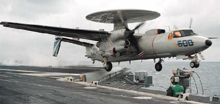
The venerable Hawkeye is the mainstay of US Navy AEW squadrons, as well as being used by Israel and Singapore. The APS-125/138/145 systems carried by subtypes of this aircraft are based on sixties UHF antenna technology, using the APA-171 radome which contains an array of Yagi antennas. Its strength is maturity and simplicity, and it delivers very good performance in its maritime environment (AEWA).
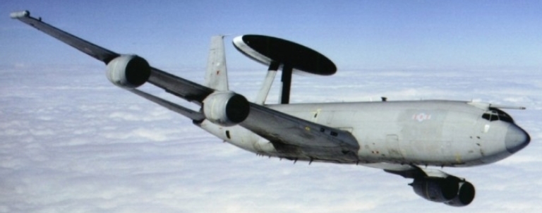
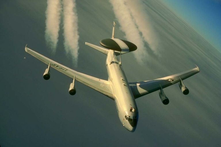
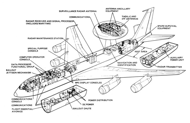
The AWACS is the flagship of US AEW technology, based on evolved versions of the 1970s APY-1 radar. The APY-1 and 2 radars are microwave E/F band systems, with mechanical rotodome scan in azimuth and phased array techniques in heightfinding. The system delivers superlative long range detection and tracking performance, but is penalised by size and weight, which impose the need for a large airframe (C-137/B-707 or widebody) and this reflects in high acquisition and support cost (AEWA).
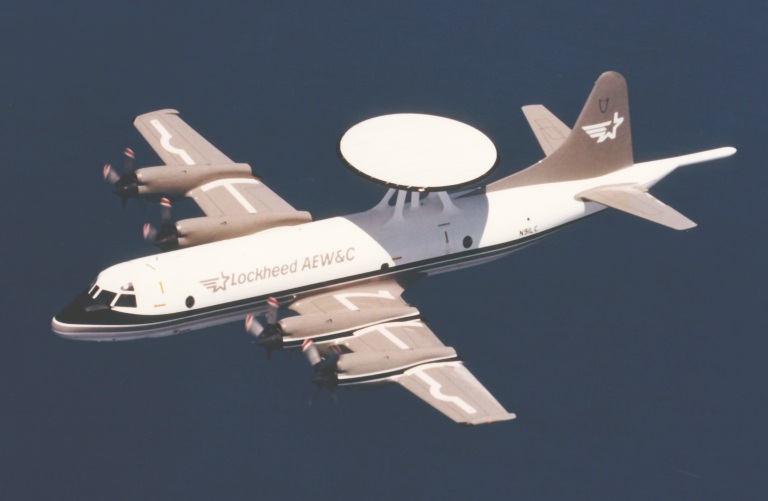
The Hawkeye's UHF radar
has been
integrated with both the Lockheed P-3 and C-130 airframes, providing a
mid range system with substantially better range and endurance
performance than the E-2C. These derivative systems exploit the
additional airframe volume available and use larger and newer computer
and display technology, in comparison with the cramped E-2C airframe.
The best known phased
array radar
in use today is the US Navy's SPY-1 Aegis, a large passive array system
fitted to Ticonderoga class cruisers. The large SPY-1 has four 3.65 x
3.65 m arrays, each with 4100 elements, and can concurrently track
several hundred targets at a range of altitudes. Designed to counter
saturation attacks by several hundred anti-ship cruise missiles, the
radar relies heavily on its ability to flexibly allocate its system
computing power to best advantage, and vividly illustrates the
potential
of modern phased array technology (LM Photo). Part 2 Active phased array antenna technology promises significant improvements in AEW&C platform performance. While the technology base has yet to mature, the first designs using this technology are beginning to appear. AEW&C using Active Phased Arrays While the application of active arrays to AEW&C systems has been under discussion for many years, only two designs have been built to date and the technology has yet to reach full scale operational deployment. Applying the active array to an AEW&C platform introduces some interesting problems with antenna placement. Conventional AEW&C systems have traditionally employed a rotodome, the characteristic saucer shaped radome which covers a conventional antenna, the rotodome rotating in order to scan 360 degrees about the platform. The placement of the rotodome on pylons, elevated well above the aircraft's fuselage, ensured that the antenna had an unobstructed field of view about the aircraft. This was achieved at considerable cost in weight, as the fuselage required strengthening to carry the structure, which itself wasn't featherweight. In typical designs, the rotodome is designed with an aerodynamic profile which produces, under cruise conditions, lift equal to the weight of the rotodome assembly, thus alleviating structural loading in cruise, but not necessarily in other configurations, unless the rotodome is built to tilt and thus change the AoA of its aerodynamic section. The rotodome arrangement is readily applicable to active array systems, as a four or three sided array may be fixed in the same position as the rotodome, providing 360 degree coverage and good clearance from the aircraft's structure. Lockheed have proposed a three sided array in this configuration, fitted to either a new airframe or the existing S-3 Viking airframe, to meet USN E-2C replacement requirements. The three or four sided array arrangement may be applied to any airframe able to accommodate a rotodome, and may well become the standard in years to come. Its only significant failing is that it retains much of the cost and weight penalties of the rotating rotodome. Another configuration derived from this idea is that of the Swedish Ericsson Erieye, which uses a two sided array in a beam shaped structure, carried above the fuselage of a twin engined commuter airframe. The two sided array used in this arrangement is almost as long as the APY-2 antenna of the AWACS, potentially providing similar angular resolution performance at range, on a very small airframe. This arrangement however suffers from an obvious and significant operational limitation, as it cannot provide 360 degree coverage, using conventional active phased array technology. With each array scanning a 120 degree sector, the two sided array has a 60 degree blind sector over the nose and the tail of the aircraft, and degraded antenna performance beyond 45 degrees off the beam of the aircraft. With Sweden's compact geography this would probably not be an issue, as multiple platforms would cover a single area, and operating in pairs, the aircraft could patrol in two racetrack orbits set 90 degrees apart to provide overlapping coverage. The success of this scheme then devolves down to the capability of the computer datalink networking which links the platforms to each other or the ground air defence centre, to ensure that a comprehensive picture of the air situation exists at whatever is the central command post. In a heavy ECM environment, where platform to platform or platform to ground datalink function is interfered with, the two sided array has thus a major limitation. Producing a three or four sided array with similar array length results in a structure with a size comparable to an E-3 AWACS radome, which in turn requires at least a 737 sized aircraft to carry it, thereby largely defeating the apparent cost advantage of the linear array concept. A possible resolution would be the use of a supergain array, where the ultimate size of the blind sector would be determined by the array's module parameters and array length. Another alternative which exists is the use of a rhombic four sided array geometry, with a 60-120-60-120 degree arrangement of arrays. While the rhombic arrangement will provide full 360 degree coverage, its effective antenna length is halved in the nose and tail sectors. The result is a compromise between the bulky but excellent four or three sided array, and the compact but partially blind two sided array. No publicly discussed proposals to date have involved the rhombic arrangement. An idea which has created some excitement in the engineering community is the concept of conformal active arrays or "smart skins", where active arrays are embedded in the skin of the aircraft, thus avoiding the structural, aerodynamic and weight penalties of an external radome. However, close examination of most existing airframe designs suggests they may not always accommodate this concept without some other penalties, such as coverage limitations like those suffered by the two sided array concept. The Israeli Phalcon system, which uses a B-707 airframe, was reported initially to have been the first implementation of this scheme. The aircraft's public debut has however shown this not to be true, as the aircraft uses fuselage mounted boxes for its main sidelooking arrays, and a nose mounted radome for a smaller forward looking array. The fuselage mounted linear arrays provide for excellent coverage over the beam aspect 120 degree sectors, but the nose and (reported optional) tail mounted arrays which "plug" the holes in beam array coverage are much shorter due fuselage diameter and thus would suffer a major loss in resolution performance fore and aft. Again the use of supergain array techniques could alleviate this problem. As with two sided and rhombic array configurations, the Phalcon arrangement may or may not be suitable for a given operational environment. Where the threat axis is defined unambiguously and the aircraft's patrol racetrack can be aligned appropriately, the coverage limitations may not be of significant importance. Where the threat can approach from multiple axes concurrently, full 360 degree coverage is almost mandatory. Westinghouse's MESA system which is currently in development, uses a podded arrangement of sidelooking linear arrays carried by a C-130, with some reports suggesting that supplementary nose and tail arrays could be fitted to plug nose and tail coverage. Other alternatives do exist. An arrangement publicised by Boeing for the now defunct USN E-X program involved the use of an airframe with a trapezoidal (diamond shaped) wing, with arrays embedded in the wing surfaces to provide 360 degree coverage. The S-3 sized aircraft had been proposed to replace the E-2C. Recent budget cuts have put its future very much in doubt. The dilemma faced by designers is simple: active arrays provide the potential for a small airframe to have E-3 AWACS class antenna performance, however antenna coverage requirements will force the use of a either a mast mounted radome or a new airframe geometry, both negating the potential cost advantage offered by the antenna technology. Other alternatives may yet exist, but investigating their suitability will require some effort by airframe manufacturers. Most modern airliner airframes have a wing sweep of about 60 degrees, which suggests that the leading edges of the wings have the almost ideal geometry to accommodate conformal arrays. A six to eight metre conformal array embedded in the leading edge, inboard, would automatically provide two sides of the three sided array configuration. The problem is that this would preclude the use of leading edge lift devices over at least 30% of the span, and also preclude the use of wing mounted engines, which would obstruct the array's field of view. The unresolved issue is the third side of the array, which could only be implemented by placing an array on the tail of the aircraft. A six to eight metre array length will require, by default, a beam structure of similar size. Closer examination of available airframes suggests that those with aft mounted engines (B-727, MD-80) would be geometrically most suited to leading edge array placement, but the positioning of the powerplants would cause difficulties in positioning the tail array. The optimal geometry would see engine pods mounted above the wings (cf VFW-614), and the tail array beam structure fitted to the end of the fuselage, or at the top of the vertical stabiliser. The scale of change would again force a new airframe design, or substantial rework of an existing design. The application of supergain array techniques could of course alleviate many of these difficulties, and it remains to be seen how soon this technology becomes adapted to an AEW&C application. Clearly as the technology of active phased arrays matures, designers will settle upon the most suitable configurations, but as is often the case, the simple and orthodox solutions may ultimately prevail simply because they were a good idea in the first place. The pylon mounted radome may be with us for some time to come. The Australian Perspective Australia has some unique problems in acquiring its future AEW&C capability. These revolve primarily about the operational requirements associated with the range of missions to be performed, further complicated by the geography of our landmass. Projected RAAF AEW&C operations can be basically divided into the support of air defence (DCA or Defensive Counter-Air), and the support of maritime operations and OCA (Offensive Counter Air). Existing doctrine is focussed on DCA (AAP1000-Ch.5). Local air defence of point targets can at a minimum, be performed by a smaller aircraft with lesser radar range, the requirement being centred on the ability to quickly get an aircraft aloft to a station within 200 NM of the runway in use, and to provide 2-4 hours of time on station. Given the concentration of potential targets in the North into specific areas and potential threat axes, 360 degree coverage may not be a mandatory requirement. Supported by long range threat warning from Jindalee, this mission can be performed readily by a smaller twin engined aircraft. The proximity to a land base means that the requirements imposed insofar as Command/Control/Communications go are modest, because land based facilities may be used to support the mission. Wider coverage of the large expanses of the North would however preclude this approach. Providing AEW&C support for DCA in the air-sea gap, maritime operations and OCA becomes a more demanding affair, as the area of operations may be several hundred nautical miles from the operating base, over the ocean, out of the reach of land based UHF comms and exposed to enemy air attack from many axes. These conditions impose the requirement for considerable range and endurance, to ensure that the AEW&C aircraft can remain on station for a substantial time, and also demand comprehensive C3 capability and 360 degree radar, IFF and ESM coverage. Good radar range is also to an advantage, as is transit speed to station and inflight refuelling capability. All AEW&C systems in use today reflect these operational requirements. The E-3 has superb radius, endurance, radar coverage and a comprehensive C3 suite, which allows for wholly autonomous operation as an airborne command post. The former Soviet Mainstay was designed to a similar requirement. The E-2C, optimised for local air defence in the maritime carrier environment, has limited range, endurance, C3 capability and radar performance, although it does provide the necessary 360 degree coverage. The SAAB-2000/Erieye has endurance and range in the class of the E-2C, limited C3 capability, and limited coverage, reflecting the local air defence requirements of the congested airspace of the Baltic, and predictable threat axes. In the Australian context, the question is whether we can effectively capitalise upon the emerging technology of active arrays. The RAAF in defining its AEW&C requirement will ultimately have to decide whether to opt for a twin engined system limited to localised DCA operations, closely coupled to ground C3 facilities and hence depart from established doctrine, or whether to opt for an extended AEW&C umbrella satisfying existing DCA doctrine and encompassing RAAF OCA and RAN operations, and hence select a longer ranging four engined aircraft capable of performing as a self contained command post. Existing RAAF DCA doctrine (AAP1000-5.41,5.42) stresses the latter approach. The central question in this matter is whether the RAAF will define its requirement in the context of recent doctrine, opting for a longer ranging platform, or whether it will yield to the inevitable financial pressure from the government to select a smaller and less capable aircraft. The selection of off-the-shelf candidates which meet stated doctrine and obvious requirements is both limited and split between older conventional technology and newer array technology. The alternative would then be a custom integration exercise, combining active array radar with a platform and array geometry not necessarily used at this time by the radar vendor. What is significant in this context is that judicious choice of airframe and array geometry could minimise integration costs, while providing scope for domestic integration work which would in turn bolster our domestic defence industry, and ease longer term support costs for the design once in service. It is central in this debate that the government recognise that short term acquisition cost advantages may not translate into a cost or operational advantage over the whole life cycle of the AEW&C system, and hence that the government does not pressure the RAAF in the direction of short term expediency. Active array technology promises major gains in the capability of both medium sized and smaller AEW&C systems, but to capitalise fully on these gains will require further integration effort. Australia has in many senses a unique operational environment and it would not be wise to bend requirements to fit established and very much development systems. We can hope the government will recognise this when it eventually proceeds with the AEW&C acquisition.
The Boeing E-3 AWACS was the first AEW&C platform to use a limited amount of phased array technology in its APY-1/2 surveillance radar. The APY-1/2 utilises a slotted planar array which scans azimuth mechanically and height electronically. With the closure of 707 airframe production, Boeing will integrate the system with a newer widebody airframe.
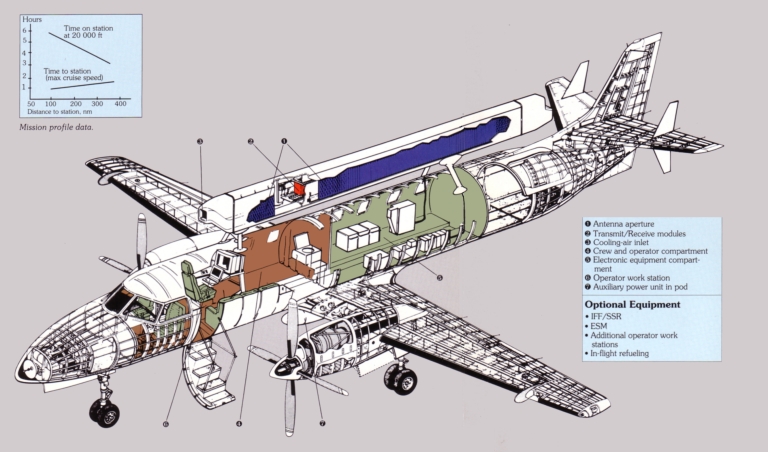
The Ericsson Erieye system uses an active phased array radar mounted in a two sided array geometry. The whole array is contained in a large beam shaped structure carried above the fuselage of a commuter twin airframe. The limitation of the two sided array is that it can only cover two 120 degree sectors abeam of the aircraft, leaving 60 degree blind sectors over the nose and tail of the aircraft, and reduced antenna performance from 45 degrees off the beam aspect. Another limitation stems from the use of an airframe too small to accommodate a comprehensive self contained command, control and communications system, and other sensors such as a capable ESM and track association system.
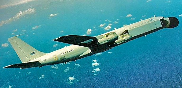
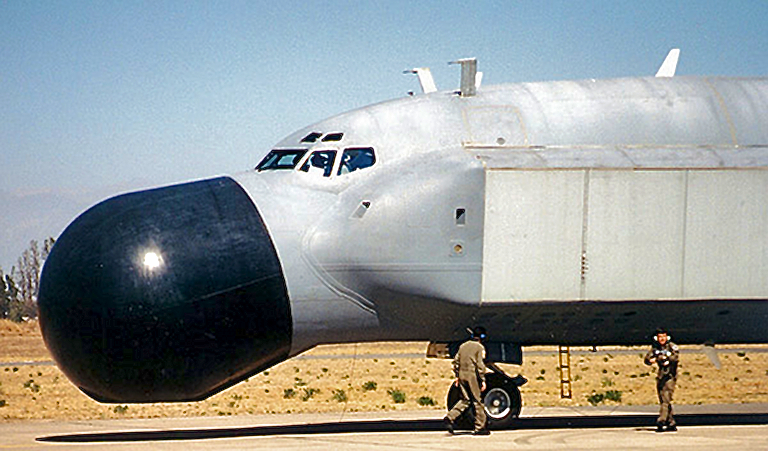
The Israeli IAI EL/M-2075
Phalcon is the first
full scale application of phased array technology, using arrays along
the fuselage and under the nose and tail. While providing full 360
degree coverage, the smaller size of the nose and tail arrays will
limit
angular resolution in the nose and tail sectors, thus degrading system
performance in these areas. While cheaper than external pylon mounted
radomes in terms of structural modifications, conformal arrays require
suitable airframe geometry if they are to be used to full advantage
(IAI images).
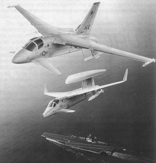
This AMSS Lockheed proposal for an E-2C replacement depicts a three sided array geometry. Three sided and four sided arrays offer 360 degree coverage without significant degradation in angular resolution against azimuth, but incur the cost, weight and drag penalties of the radome structures. At the time of writing no design using this geometry has been flown. |
|||
|
|||||||||||||
|
|
|
|
|
|
|
|
||||||
|
|
|
|
|
|
|
|
||||||
|
|||||||||||||
| Artwork, graphic design, layout and text © 2004 - 2014 Carlo Kopp; Text © 2004 - 2014 Peter Goon; All rights reserved. Recommended browsers. Contact webmaster. Site navigation hints. Current hot topics. | |||||||||||||
|
Site Update
Status:
$Revision: 1.753 $
Site History: Notices
and
Updates / NLA Pandora Archive
|
|||||||||||||
|
|
Tweet | Follow @APA_Updates | |||||||||||
|
|
|||||||||||||
|
|
|||||||||||||