|
||||||||||||||||||||||
 |
||||||||||||||||||||||
 |
 |
 |
 |
 |
 |
 |
 |
|||||||||||||||
 |
 |
 |

|
 |
 |
 |
 |
|||||||||||||||
 [Click for more ...]") |
||||||||||||||||||||||
| Last Updated: Mon Jan 27 11:18:09 UTC 2014 | ||||||||||||||||||||||
|
||||||||||||||||||||||
|
||||||||||||||||||||||
|
||||||||||||||||||||||
|
|
|
|
|
|
|
|
|||||||||||||||
|
|
|
|
|
|
|
|
|||||||||||||||
|
||||||||||||||||||||||
| Last Updated: Mon Jan 27 11:18:09 UTC 2014 | ||||||||||||||||||||||
|
||||||||||||||||||||||
| Helmet
Mounted Sights and Displays |
| Air
Power International, August 1998 by Carlo Kopp Part 1 |
|
The Helmet Mounted Sight (HMS) or Display (HMD) is a relatively recent addition to the fighter cockpit. The first devices in this category emerged during the late seventies, as an aid to targeting second generation heatseeking missiles. Given the limitations of both sight and missile technology of that period, the HMS slipped into obscurity for several years, only to be resurrected with the advent of fourth generation heatseeking missiles (WVR AAMs). At this time the HMS and newer, more capable HMDs are seeing a resurgence in the marketplace and can now be expected to become a standard feature in the cockpit of any new build fighter aircraft. The fundamental idea behind all HMD/HMS designs is that of using the pilot's Eyeball Mk.1 as a cueing device to direct a missile seeker at a target, to facilitate a rapid lock and missile shot. This was not a very strong requirement with second and third generation heatseeking missiles, since the capable Air Intercept (AI) radars which proliferated with the teen series (and teenski series) fighters typically had several dogfighting modes which were designed to rapidly acquire and track a target. The missile seekers were "slaved" to the antenna boresight, and thus once the radar locked on to the target the missile seekers would also lock very shortly thereafter. Each missile would be fed with an elevation and azimuth signal produced by the radar, and these signals would be used to steer the missile seeker direction relative to the airframe. When the first fourth generation missiles appeared, the Soviet Vympel R-73 (AA-11 Archer) and shortly thereafter the Israeli Rafael Python 4, it was clearly apparent that with very large off boresight angles, typically in excess of 60 degrees of arc, the AI intercept radar would no longer be adequate. The reason was simple, in that most antennas could not be easily slewed to angles beyond about 60 degrees. Space under radomes was limited, radome designs not optimised for beam quality at large off-boresight angles, gimbal design limits and servomotor slew rates all contributed to this situation. Last but not least, the cost of retrofitting large numbers of radars would not be trivial. And with the latest fourth generation missiles, like the AIM-132 ASRAAM, the missile itself could be fired over the shoulder at targets in the aft hemisphere. Therefore the HMS idea was resurrected. At this time many manufacturers are producing or developing such devices. Notable examples are the ELBIT DASH series, the derived VSI/Kaiser JHMCS, and designs by Pilkington Optronics for the Eurofighter, and Sextant Avionique for the Rafale. Existing users of Flanker and Fulcrum employ a Russian HMS design. Technology Issues In Helmet Mounted Sights and Displays While the idea of using the pilot's helmet to point a missile seeker is conceptually simple, implementation can be often quite tricky. A number of issues must be addressed for such a design to be robust and deliver the performance required. Key design issues can be summarised as:
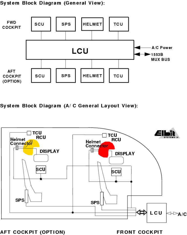
Clearly these are non-trivial requirements, and should a design fall short in any area, its utility may be seriously impaired. As a critical component in the close-in weapons targeting loop, failure to perform could cause th loss of a fighter and a pilot in combat, an expensive proposition indeed. Head Position Sensing The starting point for the discussion of HMS/HMD designs must be the area of position sensing, since it bears directly on issues such as accuracy, slew rate, field of regard, weight and robustness. A position sensing system must be capable of measuring the elevation, azimuth and tilt of the pilot's head relative to the airframe with the required accuracy, even during rapid head movement and at some very odd angles. Moreover, this assumes that the helmet "boresight" is the reference direction to which the missiles are to be pointed. Further on this later. Two basic methods are used in current HMS/HMD technology - optical and electromagnetic. Optical systems employ infrared emitters in the cockpit (or helmet) and position sensing infrared detectors on the helmet (or cockpit), to measure the position of the pilot's head. The principal limitations of this approach are the potential for a restricted field of regard, and potential sensitivity to sunlight entering the cockpit. The most popular approach in the West is the use of electromagnetic sensing. Designs based upon this idea exploit the basic physics of alternating electromagnetic fields, as commonly used in electrical transformers. A coil placed in an alternating field will produce an alternating electrical voltage the magnitude and sense of which depends upon the orientation of the coil within the field. If the coil is aligned with the plane of the field, th voltage is at its maximum, if the coil is aligned at a right angle the voltage is zero. In practice a design will use one or more fixed field generator coils within the cockpit to create the electromagnetic field, driven by a high current source, and a sense coil will be embedded in the helmet. The voltage produced by the sense coil is then fed into a black box of electronics which produces the angle measurement. Since we need to generate two or three angular measurements at the same time, we need to double or triple the number of field generator and sense coils, and orient each set at right angles to the other. Sounds complicated ? That is not all that is required. A sense coil at some arbitrary angle will be producing voltages from two or three mutually orthogonal fields, yet we need to be able to sort them apart. The simplest approach is to drive the three sets of field coils with slightly different frequencies, and then use notch filters in the electronics to separate the measurements for the three axes. In this manner, all three coils can be used to measure all the fields. Electromagnetic sensing is not without its warts. A big issue is placement of the field generator coils within the cockpit to provide proper coverage and a suitable field of regard. Another issue is preventing the fields from coupling into wiring associated with other systems in the cockpit and thus causing havoc. Eighties designs used 60 Hz fields and analogue processing, but the latest third generation technology employs 240 Hz fields and digital processing, to improve slew rates and accuracy. Helmet position measurement of suitable accuracy maketh not a HMS/HMD alone. Helmet Optics The other important issue is that of providing the pilot with a reference reticle to place over the target. The direction of the line between the reticle and the pilot's eye is the line of sight (LOS) between the aircraft and the intended target. The simplest strategy used here is that employed in the US Navy's seventies VTAS (F-4N/AIM-9H), which is a simple mechanical "ring and bead" style sight, attached to the front of the helmet. While it is simple to do, it by its nature will always be out of focus relative to the target, which is optically at infinity. Also, depending on the mounting method, it may move under G load and introduce an unwanted angular error. The next step up is to use a flat optical combiner glass, based on the same principle as a WW2 optical gunsight, and project a simple optically collimated reticle, focussed at infinity. This adds some weight to the helmet, but solves the problem of reticle focus. A light source such as an LED with a suitable lense package mounted in the top of the helmet solves this problem. Just as the optically collimated gunsight evolved into the HUD, with the incandescent bulb replaced by a Cathode Ray Tube (CRT), so the nineties have seen the introduction of embedded CRTs into helmets, thus transforming the HMS into a HMD. Modern HMDs employ typically a compact pencil shaped CRT embedded in the helmet, and suitable optics to focus the CRT image on to the pilot's visor. Focussing at infinity is often performed by matched visor shape (ie curvature) and clever optics. Using this arrangement, a field of view between 10 and 30 degrees can be readily accommodated. With a CRT the pilot can be presented with proper symbology, not just a circle or set of crosshairs. Missile status data, seeker acquisition envelope and critical flight data such as load factor, speed, AoA, altitude, Mach number and horizon may be presented. Cueing boxes produced from radar and RWR/ESM data can be used to mark the position of a target at the limits of visual range. More advanced HMDs can also project raster imagery for the pilot, derived from an external steerable FLIR or an NVG image intensifier tube(s) embedded in the helmet. With the availability of Platinum Silicide near infrared and Indium Antimonide mid infrared single chip Focal Plane Array imagers, the long term outlook is that a HMD can also provide the pilot with night vision over a wide field of view. The most problematic issue at this time with fighter HMDs is The other major problematic issue with HMDs is that the user must keep his/her eye always aligned with the sight, and thus the natural combination of head and eye movement used to track a moving object must be unlearned, and a new "head only" tracking motion learned. Since the position of the helmet is what is used to point the missile, pilots will have to develop even greater neck musculature. The technology is far from its limits at this time. The virtual reality technology base, much better funded from commercial sources, has produced a number of interesting ideas which are likely to find their way into fighter helmets. One such idea, which has been demonstrated in the laboratory, is direct retinal projection. In schemes based on this model, a small mirror is mounted in front of the eye. A low power laser, or rather a set of three (red, green, blue) lasers are bounced off the mirror directly through the pupil to project a raster scan image directly on the retina. The light beam is scanned by a tiny piezo-electric actuator, which deflects the mirror at a very high speed. While this technology is claimed to provide the potential for image resolutions of 8000 x 4000 pixels, existing technology is limited to that of a VGA class computer monitor. Safety is needless to say an issue, since the failure of the mirror actuator coul burn a spot in your retina, indeed existing prototypes have elaborate fail sense mechanisms to shut off the laser beams in the event of deflection system failure. Problematic issues remain with direct retinal projection. One is that the existing head only tracing motion problem is not solved. The other the is potential for eye fatigue due to the retina being driven with an intense light source, and thus requiring recovery time after use. Another idea from the virtual reality world which could prove to be useful for HMD designs is eye tracking, or sensing the direction the eyeball is looking at, relative to the direction of the head. A typical eye tracker will combine a miniature CCD camera and an infrared LED to illuminate the pupil. By measuring the changes in shape and position of the pupil (ie an ellipse changing its proportions and position) it is possible to measure the direction the eye is looking in, with very reasonable accuracy once calibrated. Figures cited are as good as tens of seconds of arc. Combining measurements of head position and eye position would solve the problems inherent in existing HMD technology, since the symbology and weapon boresight could be slaved to the direction the pilot is looking in, thus retaining existing (instinctually programmed) human tracking behaviour. The impediment at this time to the adoption of eye tracking into existing CRT projection HMDs is the limited field of view of the CRT projection optics. Future HMDs with wider field of view optics will be capable of exploiting eye tracking techniques. In Part 2 of this feature we will survey some representative HMDs. Part 2 In Part I of this article we explored the fundamentals of Helmet Mounted Sights and Displays, examining the operational issues and technology base, and the most likely future directions for this technology. In this final part, we will explore some representative designs. Historically, the first HMS to see wide use was the US Navy's VTAS, fitted to late model naval F-4N/S Phantoms equipped with the AIM-9H Sidewinder missile. With the retirement of the Phantom form US Navy service, the VTAS also vanished. The most widely used HMS today is the first second generation optically sensed Russian design, developed to support the Vympel R-73/AA-11 Archer missile carried by the MiG-29 Fulcrum and the Su-27 Flanker, and built to attach to the ZSh-5 series Russian helmet. The combination of the HMS and R-73 missile provided the Soviets with a close combat capability significantly better than that provided to the West by the AIM-9 Lima/Mike missiles, cued by an air intercept radar. The West responded to this development unusually late, the delay caused to some degree by the post Cold War collapse of the US-European ASRAAM program, which disrupted and split the development of Western 4th Generation AAMs into a number of separate programs. The only Western nation which responded to the Archer/HMS in a timely manner was Israel, with the IDF deploying the capable Rafael Python 4 AAM and the complementary Elbit DASH GEN III HMD during the early nineties. At this time the only combination of HMD and 4th Generation AAM in frontline operational service is the Israeli DASH III / Python 4 package. Significant development effort is under way in the US, UK, and France to field 4th Generation AAMs and supporting HMDs. The US is working on the Raytheon AIM-9X, which retains a variant of the 4.5" Mk.36 rocket motor and the existing missile warhead, but employs a new Focal Plane Array seeker and a thrust vectoring tail control package. A joint venture company, VSI, formed by Elbit and US display maker Kaiser Electronics, is currently developing the Joint Helmet Mounted Cueing System (JHMCS) to equip USAF, USN and USMC aircraft with a HMD to support the AIM-9X, early after the turn of the millennium. The UK decided to go it alone after the collapse of the multinational ASRAAM program, and followed through with a wholly British design for the new AIM-132 ASRAAM. The new missile is extremely fast, competitive in range with many medium range BVR missiles, and employs a variant of the same Focal Plane Array seeker as is used by the US AIM-9X. The ASRAAM will be carried by a wide range of RAF fighters, the RN Sea Harrier, the RAAF F/A-18A/B and possibly the RAAF F-111C/G. To support the ASRAAM on the new Eurofighter, Pilkington Optronics are designing a new and highly capable HMD, which is claimed to include embedded NVGs. The French, traditionally very independent, did not buy into the ASRAAM program, and went it alone to develop the thrust vectoring Matra MICA missile for the new Rafale, and retrofit to older French fighters. A new HMD is being developed to support the MICA, by Sextant Avionique. Sextant's Topsight is without any doubt the most futuristic looking of the current crop, and is designed as an integral embedded unit. Other nations are also working in this area, and the Russians are continuing to develop their technology base, although details have been generally sketchy. The outlook at this time is that by 2005 advanced HMDs will be widely available, from all major arms suppliers. An international customer will therefore be able to acquire this technology at a competitive price, for arbitrary combat aircraft. Integration will be mostly via the standard Mil-Std-1553B bus, facilitating tie-in to existing avionic architectures. Most of the integration effort will involve software additions to the mission computers. The Elbit GEN III Display And Sight Helmet (DASH) As noted previously, the Elbit DASH III is the first of the current crop of Western HMDs to achieve operational service, and is currently deployed on IDF F-15C, F-16C and F-15I aircraft. The DASH III has been offered to export customers, and provides in part the technology base for the US JHMCS. For these reasons, it deserves careful examination. The evolution of the DASH III began during the mid eighties, when the IAF issued a requirement for the DASH GEN I HMS, to be fitted to the F-15 and F-16 aircraft. The first generation analogue signal processor for this design entered production around 1986. It was followed in development by the improved GEN II design, which was not produced in volume. The prototype of the GEN III helmet was tested during the late eighties, and entered production with a 50 Hz analogue signal processor during the early to mid nineties. The current production variant is certified on the F-15C/D, the F-16C/D, the F-15I, the F/A-18C and F-5E/F, the latter intended for export clients. The DASH GEN III is an example of an "embedded" HMD design, where the complete optical and position sensing coil package is built into a standard helmet form factor, in this instance either the USAF standard HGU-55/P or the Israeli standard HGU-22/P. The DASH III complies with the safety and ergonomic parameters of the standard HGU-22/P or HGU-55/P. The helmet is customised to individual pilot head shapes and sizes using either poured foam or thermal plastic liners. Once the helmet is fitted to the pilot, the optics are adjusted to provide the proper exit pupil size for the pilot, since individual pilot's eyes will differ slightly. The DASH III can accommodate pilots who must wear corrective spectacles. Standard oxygen mask sizes and attachments are supported, and the design is compatible with the US PHIM NBC protection system. All up weight for the DASH III is 1.65 kg for the larger helmet size, and the helmet centre of gravity meets USAF/USN standards. An umbilical cable carries power and video drive signals to the internal helmet electronics, and position sensing signals from the helmet to the signal processor box. The umbilical is provided with a quick disconnect connector to provide for safe ejection. The 8.5 kiloVolt high voltage supply for the helmet's Cathode Ray Tube (CRT) is embedded within the helmet, so that no high voltages are present on the umbilical. The tube and supply are embedded in the back of the helmet. The DASH projects the CRT image via a folded optical path directly on to the spherical section visor. This technique was specifically chosen to avoid difficulties with projection optics and the need for additionally tight tolerancing on non-spherical curved visor shapes. The imagery is collimated, so the pilot need not refocus to read the symbology. The DASH provides a solid angle Field of View (FoV) of 20 degrees, with a 15 mm exist pupil for the optics. All symbology is calligraphic, produced by a programmable stroke generator, and a green phosphor is employed. The DASH is tightly integrated with the aircraft's weapon system, tied in via a Mil-Std-1553B multiplex bus. The core of the DASH avionic package is the LCU (Line of sight Computer Unit), which contains the electronics to interpret the output from the position sensing coils in the helmet, the stroke generator electronics to drive the CRT tube, a supervisory processor, and a 1553B bus Remote Terminal interface. The LCU communicates over the bus with the aircraft's Mission Computer. Software running on the Mission Computer interrogates the LCU to get angular measurements in order to cue weapons, and continuously updates the LCU with critical flight information and status information for display to the pilot. The symbology is all programmable in software, and a client Air Force can essentially employ whatever it chooses to. Elbit have not disclosed the number of lines of code in the LCU and Mission Computer interface libraries, although it is know that much of it was programmed in C and Assembly language, not untypical for embedded designs where speed is an issue. Integration of HMD modes, HOTAS controls, and weapon system modes will be done in the Mission Computer OFP (Operational Flight Program), and will be specific to a customer's requirements. Growth capabilities for the DASH series of helmets will center upon a new LCU design, running at a much faster 240 Hz sample rate, and employing fully digital processing techniques. Of some interest is the magnetic mapping of the cockpit. Ferrous and conductive materials in the seat, cockpit sills and canopy will distort the magnetic field and would if not compensated, introduce angular errors into the measurement. Therefore, the DASH is designed to compensate for this. A robotic fixture is clamped into the aircraft's cockpit at the time of system installation, and a fully automated program is used to measure the magnetic fields in the cockpit and program the LCU with compensation parameters. I had the opportunity to handle a DASH helmet at a trade show stand, and excluding the slightly higher weight and bulged visor, the helmet is hard to differentiate at first glance from the standard HGU-55 series helmets. The strength of the DASH III lies in its maturity, and compact form factor which in no way compromises a tight canopy. Its limitations are characteristic of that generation of helmets, and lie in a modest sampling rate and inability to support raster scanned imagery for FLIR/IRS&T display. It is likely that growth variants of the helmet will be able to accommodate raster imagery, and the faster 240 Hz LCU is in the pipeline. Joint Helmet Mounted Cueing System (JHMCS) Without any doubt the most important HMD in the development pipeline is the JHMCS, intended as a tri-service design for use by the USAF, USN and USMC on a wide range of tactical aircraft. At the time of writing the JHMCS was to be used on the F-15, F-16, F-18 and F-22. The JHMCS can best be described as the offspring of the DASH III and the Kaiser Agile Eye and VCATS HMDs, and is under development by Vision Systems International, a company jointly owned by EFW/Elbit and Kaiser. VSI is at this time responsible for all three HMD designs. Unlike the embedded DASH, the JHMCS is a clip-on package, which can be latched into position with one hand in flight, on a modified HGU-55/P, HGU-56/P or HGU-68/P helmet. The JHMCS is a much more advanced design than the DASH, and builds on the collective technology base of Elbit and Kaiser. It employs a newer, much faster digital processing package, but retains the same style of electromagnetic position sensing as the older DASH does. The CRT package is more capable, but remains limited to monochrome presentation of calligraphic symbology. While the manufacturers have declined to comment, it would appear that the JHMCS will provide support for raster scanned imagery to display FLIR/IRS&T pictures for operations in poor visibility or at night. The photograph of the helmet separated from the Display Unit clearly illustrates the hihg voltage coaxial and discrete/serial connections via the umbilical, which is embedded in the helmet. Unlike the DASH series, the high voltage supply is not embedded in the helmet and feeds up via the umbilical, through a quick disconnect inline high voltage rated connector. An attachment is provided to allow a NVG package to be clipped on during flight. The JHMCS will provide a 20 degree FoV for the right eye, with an 18 mm exit pupil. It is expected that the JHMCS will be in production shortly after the year 2000, and will be supplied first to units intended to deploy the high off-boresight capable AIM-9X missile. Sextant Topsight and TopNight Sextant Avionique has developed a family of current generation HMDs for deployment on the Rafale and late model Mirage 2000 fighters. The futuristic appearance of these helmets results from the use of a flush external face guard, contoured so as not to obstruct the pilot's FoV yet to fully cover the oxygen mask. Sextant claim that their helmet geometry results in no impairment of the pilot's peripheral vision. The TopSight is the lightweight (1.45 kg) air combat HMD developed for the Rafale fighter, and like its US/Israeli competitors, provides a 20 degree FoV for the pilot's right eye, and calligraphic symbology generated from target and aircraft parameters. Electromagnetic position sensing is employed. The TopNight is a raster and calligraphic binocular HMD, designed specifically for adverse weather and night air to ground operations. While in general appearance it resembles the Topsight, it is heavier at 1.8 kg and employs more complex optics to project collimated imagery overlaid with symbology, providing a 30 x 40 degree FoV. Sextant have been somewhat shy about disclosing technical details on these designs, but it is clear from what little has been published that these HMDs differ in many areas from the Israeli/US approach to the problem. Pilkington Optronics Eurofighter Helmet The Eurofighter helmet has been kept very much under wraps, and at the time of writing the manufacturer had disclosed few details. It is known that this helmet will be capable of displaying both raster imagery and calligraphic symbology, and that provisions will be made for embedded night vision equipment. BAe have stated that the helmet is to employ the most advanced technology available at this time, but in the absence of hard data any further discussion would be entirely speculative. Delft Instruments/GEC Marconi Viper 3 NVG/HMD Whilst not strictly a symbology projecting HMD in its current incarnation, the Viper 3 is of considerable interest since growth variants are intended to have such a capability, and the basic Viper 3 design addresses long standing limitations of fighter NVG installations. Delft developed the Viper 1 and 2 HMDs which are CRT based symbology projecting devices, and decided to build on this experience by collaborating with GEC Marconi to produce an ejection safe clip-on NVG package for use on fighter aircraft. The result of this effort is the Viper 3 design, which attaches to all three standard sizes of the HGU-55/P helmet. Conventional NVGs are attached to helmets externally and are considered by many pilots to be literally a pain in the neck, since they add weight to the front of the helmet, are seldom considered ejection safe, requiring removal before punching out, and have a narrow Field of View. The Viper 3 exploits the visor projection scheme common to HMDs, and employs multiply folded optical paths to carry the imagery from a pair of 18 mm ANVIS Image Intensification Tubes (IIT) to the pilot's spherical visor. The provides the pilot with an unobstructed binocular 40 degree Field of View NVG capability on his see through visor. The IIT packages are mounted on the sides of the helmet, to provide the best possible balance for low fatigue and safe ejection. Delft claim that the imagery quality is equal or superior to that from conventional NVGs, and using the standard HGU-55/P rather than the lightweight variant, the Viper 3 package adds only an additional 15% weight. The helmet is considered suitable for loads of up to 5 or 6 G. Importantly, the optical design of the Viper 3 is such that the addition of a dichroic beamsplitter to one of the mirrors in the optical path between the IIT and visor allows the addition of a CRT to the Viper 3 design. This in turn means that the Viper 3 can grow to become a combined projection HMD and NVG package, withe addition of a CRT and head tracking sensors. The addition of a CRT will add some weight, but improve the balance of the package. The Viper 3 design solves the principal problems associated with conventional clip-on ANVIS NVGs. The only installation requirement is the modification of pitot tubes on the ACES2 ejection seat. Australia's DSTO Research Effort in Display Technology Closer to home, the rapid evolution of HMD technology has not gone unnoticed. The Air Operations Division of DSTO Aeronautical and Maritime Research Laboratory in Melbourne has built up a respectable research capability in human factors, and support this effort with a modular simulation facility at their Melbourne site. The primary focus of DSTO's activity in this area is basic or fundamental research in human factors, and is intended to develop an objective and quantitative understanding of issues in the design of cockpits, displays, symbology formats, workload effects, and ergonomics. Essentially, the science of how to best present information to an operator visually and aurally. For aural data presentation research, DSTO has built an anechoic chamber with a robotically positioned sound source, and supporting signal generators and recorders. Current activity is centred on the presentation of threat data to operators using synthetically generated sounds and spatial information. The simplest example would be a warbling threat warning indicator which the pilot hears coming from the actual bearing which the threat emitter is on. Other experiments in this area involve mapping threat information on to generic, commonly understood sounds, ie an AAA battery makes a "machine gun" sound, again on the bearing of the actual battery. This research will eventually lead to the capability to warn pilots of threats without the need to continuously scan a threat warning display in the cockpit, thus allowing the pilot to spend more time with his head out of th cockpit. The flight simulator facility, built around a core of several large Silicon Graphics computers equipped with high speed graphics adapters, and interchangeable cockpits for the F/A-18, F-111 and Blackhawk, provides the ability to simulate complex tactical situations while recording and measuring critical human factors parameters. To achieve a high degree of realism, the simulator employs high quality image generators in a half dome facility. I had the opportunity recently to sample this simulator, and can state that the objective of immersing the test subject in the simulation has been indeed achieved. The Blackhawk helicopter simulation provided much better fidelity than operational simulators I have had the opportunity to fly, both civilian and military. A notable recent project involving this simulator was a series of human factors tests using the Sextant TopNight helmet to display various forms of HMD symbology. The purpose of the project, conducted jointly with Sextant using a loaned HMD, was to explore the effects of different styles and types of symbology on pilot performance, essentially to determine the alternatives which the pilot can recognise and understand most quickly, with the lowest error rate. This is a specific area where the rate of HMD hardware development has outstripped the human factors research base, and thus there is much to be gained in researching this area. It is expected that the results of this research will be used to define the symbology formats for any future HMDs to be used by the RAAF. As we can expect that the RAAF will acquire a HMD within the next few years to support the AIM-132 ASRAAM missile, this research effort is both timely and appropriate. Conclusions Clearly the current generation of HMDs provides a significant capability improvement over earlier technology HMS'. In the longer term we can expect to see all HMDs providing raster and calligraphic modes, binocular vision, higher angular rates, wider FoV, embedded eye tracking and full colour capability. Weight and compactness will continue to be an issue with all such technology. Despite the limitations in current technology, it is quite evident that the wide scale deployment of the HMD will further reduce cockpit workloads and increase the lethality of modern fighters in close quarters combat. The vendor community's favourite line that "looks can kill" indeed holds true.
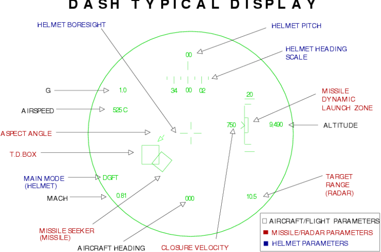
This diagram depicts typical symbology used with a DASH III HMD. The pilot is presented with critical aircraft performance data, status information on weapons, target parameters and cueing information on detected threats. The pilot can cue the missile seeker to a "boxed" target, once the seeker is locked it continues to track the target and this is displayed with a "diamond" symbol (VSI).
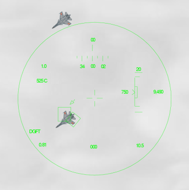
This diagram depicts the pilot's view of an engagement through the DASH III HMD. The lead Flanker is about to die from a missile shot, the attacking fighter's pilot having cued the missile seeker to lock up the target previously.
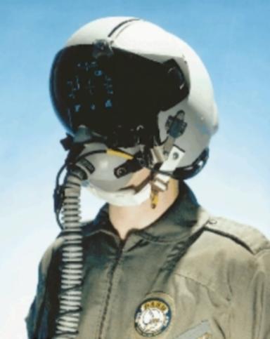
The DASH III is currently in service on the Israeli AF F-16C/D, F-15C/D/E and is available for export. The projection hardware is wholly embedded within the helmet, using a spherical visor to provide a collimated image to the pilot (VSI).
The JHMCS is planned for large scale deployment on the USAF's F-15C/E, F-16C and F-22, the USN/USMC F/A-18C/E. It is designed as a clip-on attachment to a modified HGU-55/P, HGU-56/P or HGU-68/P helmet, and will provide collimated symbology and imagery to the pilot (VSI).
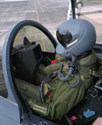
The futuristic appearance of the Rafale's Topsight E is no accident, the contoured shape of the helmet is designed to provide the pilot with a wholly unobstructed field of view. Like the DASH III and the JHMCS, the Topsight E is designed for high G combat, and projects collimated symbology into the pilot's right eye (Sextant Avionique) |
|
|
| The Viper 3 is a HMD design which optically projects the images from a pair of NVG tubes directly on to the pilot's visor. This improves image quality, removes obstructions from the pilot's field of view, and avoids the balance problems of clip-on NVGs which make them often unsafe for ejection. Growth variants of the Viper 3 are expected to include a CRT for symbology projection and head tracking sensors (Delft). |
|
|||||||||||||
|
|
|
|
|
|
|
|
||||||
|
|
|
|
|
|
|
|
||||||
|
|||||||||||||
| Artwork, graphic design, layout and text © 2004 - 2014 Carlo Kopp; Text © 2004 - 2014 Peter Goon; All rights reserved. Recommended browsers. Contact webmaster. Site navigation hints. Current hot topics. | |||||||||||||
|
Site Update
Status:
$Revision: 1.753 $
Site History: Notices
and
Updates / NLA Pandora Archive
|
|||||||||||||
|
|
Tweet | Follow @APA_Updates | |||||||||||
|
|
|||||||||||||
|
|
|||||||||||||