|
||||||||||||||||||||||
 |
||||||||||||||||||||||
 |
 |
 |
 |
 |
 |
 |
 |
|||||||||||||||
 |
 |
 |

|
 |
 |
 |
 |
|||||||||||||||
 [Click for more ...]") |
||||||||||||||||||||||
| Last Updated: Mon Jan 27 11:18:09 UTC 2014 | ||||||||||||||||||||||
|
||||||||||||||||||||||
|
||||||||||||||||||||||
|
||||||||||||||||||||||
|
|
|
|
|
|
|
|
|||||||||||||||
|
|
|
|
|
|
|
|
|||||||||||||||
|
||||||||||||||||||||||
| Last Updated: Mon Jan 27 11:18:09 UTC 2014 | ||||||||||||||||||||||
|
||||||||||||||||||||||
| Optical
Warfare - The New Frontier |
|||
|
|||
|
Electronic Warfare is a discipline characterised by rapid change, where openings and vulnerabilities are exploited quickly and always to the detriment of the slower party. As with Electronic Warfare at lower frequencies, the electronic battle at optical frequencies is equally intense and can have an equally decisive impact upon a conflict. As an instance the Russians' deployment of the Fulcrum and Flanker fighters equipped with laser ranging Infrared Search and Track sets (IRS&T) was a successful attempt to circumvent overwhelming Western capability in microwave Electronic Warfare techniques by shifting the aircraft's key fire-control sensor into the optical frequency range. This move was hardly unexpected as Russian efforts in IRS&T equipment development have been noted for at least half a decade, what is truly alarming is the lack of response to this event by Western air forces. As emerging Stealth technologies erode the capability of microwave radar based systems to provide missile guidance and fire control parameters, optical systems in the visible and infrared bands will assume an ever increasing importance. Optically guided weapons will proliferate in land, sea and air battle scenarios at the expense of conventional systems. To these issues must be added the practical implications of an air and ground environment where laser beams of eye-damaging wavelengths and power levels are used by almost every fire control system, be it air-to-air, air-to-surface or surface-to-surface. As with microwave EW, a clear understanding of the technology of electro-optical systems is essential to the conduct of offensive and defensive electro-optical warfare. The following will hopefully clarify some of the issues. Infrared Trackers The infrared tracker is the technology at the core of infrared missile warning systems, heatseeking missiles and IRS&T sets. Its function in the simplest of terms is to scan a field of view (FOV) for any sources of infrared radiation of a particular wavelength or band of wavelengths and to measure with some accuracy the angular coordinates of these sources. These sources will be exhaust plumes and airframes which radiate heat and thus infrared radiation (for more detailed discussion of the infrared signature of an aircraft, please see TE March 1982, TE May 1987). There are numerous ways of building infrared trackers, the most important of these are the reticle, rosette scanning and focal plane array techniques, which are common to heatseeking weapon guidance, infrared warning systems and IRS&T sets. In spite of their differences in construction and performance, all infrared trackers will have some features in common.
All will employ either an array of or a single detector element. A detector is a small piece of a semiconductor material which is photosensitive, ie its electrical properties will change when illuminated by light of a given wavelength. Numerous materials have been used for detectors over the last four decades, with PbS very popular in early days, later yielding to InSb. The favoured materials today are Mercury Cadmium Telluride (HgCdTe) which is unfortunately very tricky to fabricate detectors from but provides superior sensitivity to longer wavelengths and Platinum Silicide which is less sensitive but far easier to process.
The performance of any detector material is usually judged by its sensitivity over some range of wavelengths (colours). Sensitivity is a measure of the amount of electrical response the detector will provide to some given level of incident radiation, ie the more sensitive the detector material the fainter the radiation it can detect. Sensitivity will vary with wavelength as a result of quantum physical effects in the detector and more mundane considerations such as detector surface finish. The quantum physical aspect is given by the photoelectric effect where photons of impinging light or infrared excite electrons (carriers for the physics oriented reader) within the material, if the photon is energetic enough (ie its wavelength short enough) the electron will be dislodged from its place in the detector's crystalline lattice and becomes detectable as a minute electrical current. The minimum photon energy required to dislodge a carrier determines the longest wavelength detectable by the detector material and hence the lowest possible temperature target which may be detected. This is important as the infrared signature of a rocket exhaust plume, engine tailpipe, fuselage rear end and airframe all differ in peak wavelength, the hotter the target the shorter the brightest wavelength and the broader the range of wavelengths emitted (readers are advised to look up blackbody radiation in any decent physics textbook). A 2 micron band detector will thus see only rocket exhaust plumes, afterburner plumes and tailpipe cavities, a 4 micron band detector all of the above and hotter parts of the airframe from all aspects, while an 8 micron band detector all of the above and the whole airframe or even its wake. As it turns out the longer wavelength detectors must be cooled for operation, as room temperature itself will excite enough electrons in the detector to completely swamp any photoelectric current from a sought target.
Ideally the designer of an infrared tracker would seek a detector matched to the wavelength of the sought target while requiring minimum cooling. Cooling a detector is another can of worms and many techniques have been used in practice. Missiles will employ gas or thermoelectric cooling, whereas IRS&T equipment may also employ closed cycle refrigeration to reduce turnaround time. Gas cooling involves the rapid expansion of a compressed gas usually provided from a bottle installed in the launcher or launch system, as instances the Nitrogen cooled USN AIM-9D PbS detector or Argon cooled USN/USAF AIM-9L Sidewinder InSb detector. Thermoelectric cooling is achieved via the use of a Peltier heat pump, passing an electrical current through such a device cools one end of it and heats the other, the USAF AIM-9E/J's PbS detector was cooled in this fashion.
The choice of detector material cooled to an appropriate temperature will determine the sensitivity and longest detectable wavelength seen by the infrared tracker. Most detectors are sensitive to visible light due to the nature of the photoelectric effect and this can cause problems in the real world. The sun is a bright source of visible and infrared light (6000K blackbody radiator) and any highly reflective object such as a cloud will also appear as such to a tracker, this is the reason why inferior heatseeking missiles chase the sun or clouds. The solution to this problem is simple in concept although often tricky in implementation; the detector will view the outside world through an optical filter which will suppress all visible and infrared light of those wavelengths which are not desired. Filters are usually implemented by depositing very thin layers of glass with alternating refractive indices and thicknesses of the order of the wavelengths of light involved, upon the surface of the glass window used by the detector. Clever choice of thicknesses will cause an effect termed interference; undesirable wavelengths are reflected and the remainder passed. The gold hue apparent on the nose windows of infrared missiles is such an interference filter.
A cooled detector with its optical filter is the core of an infrared tracker. What remains is some mechanism to focus the incoming light on to the detector and point the detector's field of view within the tracker's field of view. This mechanism is the tracker's optics, which are often stabilised in pitch and yaw to provide a jitter free output.
The oldest and perhaps dominant optical arrangement today is the rotating reticle scheme, first put to use by the Germans on A-4 ballistic missiles. The rotating reticle scheme (see TE March 1982 for illustration) uses a rapidly spinning reticle (or mirror) which has a pattern of transparent spokes etched on half of its surface, the other being semi-transparent, the detector views the outside world through the whirling pattern of the reticle. The pattern chops all incident light and the resulting output from the detector is a train of pulses synchronised to the reticle. The pattern on the reticle is designed such that the size of the pulse train is proportional to the angular displacement of the target relative to the axis of rotation of the reticle. The remaining angular coordinate is derived from the relative timing (phase) of the pulse train relative to the reticle rotation.
The rotating reticle tracker is penalised by the need for precision fabrication of the reticle which must be exact mechanically while also often doubling up as an infrared filter, alternate construction employs a concave mirror with the reticle pattern etched on its surface. The strength of this technique lies in the simplicity of the analogue electronics required to decode the target position. Its practical limitations lie in its narrow field of view and high susceptibility to amplitude modulation (AM) jamming, the simple technique of flashing an infrared source at a rate comparable to that of the reticle rotation can cause the electronics to lock on to the jammer's pulse train and drive the tracker away from the target (as with AM jamming of conical scan radar). A newer and mechanically/optically simpler arrangement is that of the rosette scanning tracker. A rosette scanning tracker will usually employ a single fixed detector and moving optics which have a small instantaneous field of view. The optics then scan a much larger field of view in a rosette pattern, which has the appearance of a flower with multiple petals. The strength of this technique lies in the simplicity of the scanning mechanism and a minimum of hardware in the optical path; the penalty is in the additional complexity of the electronics required cf. a rotating reticle tracker.
Jam resistance of these trackers has not been discussed at length in the open literature, no doubt for fear of compromising weapons such as the FIM-92 Stinger SAM.
The newest family of optical trackers are imaging or Focal Plane Array (FPA) trackers, which will become the dominant tracker in the next decade or so. A FPA tracker will employ a planar array or field of detector elements which stare at the whole field of view simultaneously. By reading the outputs of the detectors with electronics embedded in the same chip/carrier, an image of the viewed scene can be recreated for viewing by an operator (eg FLIR applications) or analysis by an image processing computer to detect and track targets. The construction of the necessary optics is simple with no moving parts - a lense/ window/filter and a support to position the chip carrier within the required focal plane of the optics, this arrangement is thus cheap to produce, align/ calibrate and has a high tolerance for acceleration thus being very suitable for missile guidance. Four technologies are being used or evaluated for use in imaging/array trackers; Mercury Cadmium Telluride(HgCdTe), Platinum Silicide, Indium Antimonide(InSb) and Iridium Silicide.
HgCdTe is a well established material with excellent sensitivity extending down to the 8-12 micron band (cool targets, ie FLIR applications, satellite tracking, detecting stealth vehicles ) but it is difficult to fabricate arrays from because of a very large variation in sensitivity from detector to detector. Such an array will introduce clutter (noise) into the image it views and this will understandably make it more difficult for the image processing algorithm to sift targets from the background. As a result additional signal processing is usually required to compensate for array nonuniformity. At the time of writing Rockwell International were offering 128 x 128 element arrays in HgCdTe. The alternative to HgCdTe in 5.5 micron band applications (warm targets such as airframes from all aspects, vehicles, exhaust plumes) is InSb which is easier to fabricate and offers good uniformity. 128 x 128 and 256 x 256 element arrays are offered by Amber Engineering of Goleta, California, who are developing arrays for civilian and military applications.
Another alternative is the use of Platinum Silicide which is unfortunately about fifty times less sensitive than HgCdTe and is spectrally limited to the 2.5-4 micron band(ie hot targets such as aircraft/airframes, vehicles, missile exhaust plumes); its strength lies in high uniformity of array sensitivity and ease of fabrication and thus low cost, commercial Silicon fabrication techniques are used as for eg MOS memory chips. This infers another major advantage, the ability to embed within the same slab of Silicon all the necessary electronics to scan and read out the image from the array, thus radically cutting the cost and complexity of the optical system as a whole.
Platinum Silicide arrays of 512 x 512 elements are now offered by Hughes, the highly sought (by the military) 1024 x 1024 array size is expected to become available in the next two years as the technology matures. Iridium Silicide offers like HgCdTe operation in the 8-12 micron band but is very immature as a production technology today.
The choice of detector array having been made for the application, the designer of the tracker will have to select a tracking algorithm and suitable image processing computer or logic for the task. In established applications such as missile guidance (eg AGM-65A/B/D Maverick) tracking can be done with a hardwired electronic contrast lock which places 'gates' about an operator specified area of contrast in the viewed scene or image. The position of the 'gates' in time relative to the video signal (ie scanned line by line picture) from the array readout electronics then determines the angular position of the target. A newer technique is to save the image in a dedicated area of computer memory and then have a powerful processor sift through the image and accomplish the above in software; this strategy offers flexibility in algorithm performance and the ability to autonomously search for and recognise targets.
As with rosette scanning trackers little has been written in the open literature about suitable techniques for jamming imaging trackers. At a guess possible techniques could involve seduction of the tracking gate with flares (ie gate stealing) or causing the target to scintillate with phased IR jammers at its extremities (eg wingtips), this latter technique would cause jitter in a centroid tracking algorithm. Its effectiveness would be very limited, only during the terminal phase of a fighter or missile attack with the purpose of forcing a near miss just outside proximity fuse range or spoiling the gun aim. In general the passive nature of the IR tracker makes it all the more difficult to jam as the jammer has no means of directly assessing its effect on the threat as with microwave jammers. While all designs will exhibit generic and specific vulnerabilities to jamming, good intelligence and other sensors may be required to identify the IR tracker equipped threat in order to select an appropriate jamming technique. An alternative to jamming is the use of a suitable laser to blind the tracker by saturating its detector(s), this is a brute force method not unlike barrage jamming which can be very effective against trackers with a slow auto gain control response. By the time the tracker recovers the target will have drifted out of its field of view and the threat has been defeated. In the context of defeating infrared trackers, Stealth or more formally Low Observables technology is an potent alternative. A LO design will conceal its engine hot end from trackers by reducing the viewing aperture (ie range of viewing angles). This is achieved by exhaust placement (cf Northrop B-2A upper surface exhausts), shape and the use of louvres and shielding structure. Exhaust plumes are then cooled to a temperature at which the brightest infrared colours are absorbed by atmospheric carbon dioxide and water vapour over fairly short distances. The cumulative effect of these measures is that an infrared tracker can detect a LO design only from a very narrow range of angles, usually from astern/above, at relatively short range under clear weather conditions only. Tracking is only possible when these conditions are maintained, ie manoeuvre by the LO target or use of cloud will defeat the tracker. As it is most apparent, there is a broad range of tracker types available and each will have its appropriate offensive and defensive application. Offensive applications involve both weapon guidance and fire control systems. Infrared Search and Track Systems The IRS&T set has been in use, in its various guises, since the 1960s when USAF air-defence fighters such as the F-101B Voodoo and F-106A Delta Dart carried nose mounted nitrogen cooled lead selenide cross array IRS&T sets to detect high flying Russian bombers such as the Bear and Bison. The strength of the IRS&T is in its ability to detect and track a target passively and thus undetectably.
This is considered to be a major asset in air defence operations as it vastly reduces the warning time to attack on a target. In a situation where a large bomber target may carry powerful onboard jamming equipment the use of a Air Intercept (AI) radar by a interceptor will not only provide the bomber with timely warning of impending attack, it will also provide the bomber with an opportunity to defend itself by jamming. This strategy was adopted by the US Navy which equipped its F-4B air defence fighters with chin mounted AAA-4 IRS&T sensors, used in part to cue early AIM-9B Sidewinder seekers, these were deleted from later versions as the aircrafts' role shifted to air superiority/strike. The new F-14A became the Navy's principal air defence fighter and it also carried an IRS&T set, although these have been largely replaced by AXX-1 Television Camera System TV telescopes.
The Russians have certainly never been shy about copying Western designs and they too deployed IRS&T sets from the 1960s onward, fitting these to Foxbat and Flogger aircraft of the IA-PVO-Strany. While this equipment has not been publicised in the Free World it is likely to be similar to late sixties US designs, providing a 2 micron band detection capability in clear weather conditions.
The subject of greater concern is the current generation of Soviet IRS&T equipment which is fitted with a boresighted laser rangefinder and in effect provides the same fire control functions as an air intercept radar, under appropriate atmospheric conditions. The fundamental failing of the passive IRS&T is its inability to measure range to the target, although some estimate could be made given the intensity of the target's infrared signature. The ability of a Fulcrum, Flanker or Foxhound to carry out a full GCI(intercept) and missile or gun attack with electro-optical systems alone renders the hundreds of pounds of microwave jammers aboard Western strike aircraft quite ineffective.
The Soviet thrust into the area of Infrared Search & Track/Laser fire control has been paralleled in the Free World by the deployment of FLIR/laser systems such as Lantirn on Western tactical aircraft such as the F-15E and F-16C/D. Thermal Imaging/Laser Systems Forward Looking InfraRed (FLIR) is a generic term referring to the broad range of thermal imaging equipment. The first true thermal imagers appeared in the seventies when the USAF deployed a range of systems based upon the Texas Instruments family of thermal imaging modules (TE March 1984). The technology has since proliferated and is now used on almost every class of platform. Of particular interest here is its application to fire control systems used by tactical aircraft, such as the AVQ-26 Pave Tack carried by the RAAF's F-111C, battlefield helicopters, such as the TADS/PNVS turrets carried by MDC AH-64A Apache, and SAM/AAA systems, such as the Philips Trackfire . In all of these applications the stabilised thermal imaging telescope is boresighted with a laser rangefinder and thus can provide all three coordinates of a target - this allows a fire control computer to calculate a fire control solution for an unguided weapon or gun or to set up optimal release conditions for a guided weapon. The laser however also doubles up as a target designator by transmitting an appropriate pulse code. A rapidly flashing spot of appropriately coded laser illumination on a target is used to guide semi-active laser homing weapons, which home in on the laser spot. Both conventional laser guided bombs such as the GBU-10/Mk-84 and GBU-12/Mk-82 used by the RAAF and laser guided missiles such as the AGM-65E Maverick or AGM-114A Hellfire use this technique, relying on a simple four quadrant detector (ie four detectors arranged in a Maltese cross pattern) arrangement. The accuracy of these weapons is very high, with average miss distances of feet. There is however a more insidious aspect to these systems.
Nearly all laser rangefinders and designators employ Nd:YAG 1.066
micron
near infrared lasers which have both the power level and short
wavelength required to damage the human retina. Partial and complete
blindness may result from direct or indirect sighting of the beam from
such a laser. The presence of laser rangefinders on almost all armoured
vehicles, tanks and battlefield close air support aircraft and
helicopters renders battlefields optically hazardous to the unprotected
eye. The Russians have taken a particular liking to the use of laser
rangefinders as antipersonnel weapons, sweeping the battlefield ahead
of
their advancing armour to damage eyes and less robust optical fire
control sensors. The USAF had investigated this application under the
Compass Hammer program, proposing an optical tracker capable of
detecting gun muzzle flashes and directing a powerful blue green laser
at the source to blind the gunner or fire control system. A
Westinghouse
designed Advanced Optical CounterMeasures pod was successfully flight
tested in the mid eighties with planned application to the B-52,
however
no information appears to be available on deployment plans. The
countermeasure is the wearing of protective goggles, usually employing
multiple interference filters for specific laser wavelengths, all the
time by all personnel. Invisible and narrow laser beams offer no
warning
to the victim. 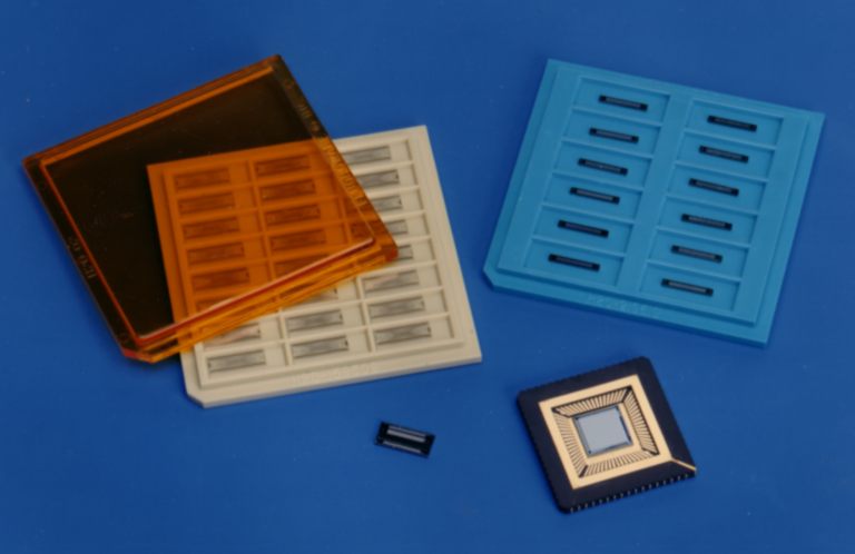 Amber Engineering InSb/CMOS Hybrid Focal Plane Array. The AE128x128 FPA in the lower right corner JEDEC 68-pin package is in effect a FLIR on a single hybrid chip. Note the vast increase in resolution compared to the smaller 64x8 arrays above (readout chip to the left), which are more typical of established thermal imaging technology. FPA technology is bridging the gap between single/multiple detector infrared trackers and the cumbersome linear array/moving mirror thermal imagers, offering vast improvements in sensitivity, stability and resolution at substantially lower unit production costs.
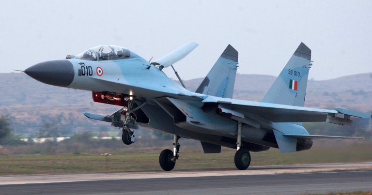
Flanker Fire Control System. Faced with the overwhelming capability of Western electronic warfare systems, the Russians fitted the Fulcrum, Flanker and Foxhound with InfraRed Search and Track/Laser fire control systems to supplement the vulnerable pulse Doppler radar. As Western tactical and strategic aircraft lack laser warning receivers, the Fulcrum, Flanker and Foxhound can engage and shoot their victims without being detected.
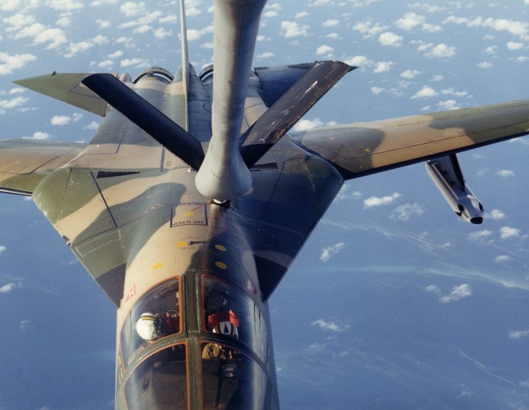
This RAAF F-111C demonstrates offensive and defensive applications of electro- optical technology. The Ford AN/AVQ-26 Pave Tack thermal imager is boresighted with a laser rangefinder/designator and tied into the bombing/navigation system, it is used for precision munition delivery and navigation. The tail mounted Cincinnati AN/AAR-34 infrared warning system employs a tracker with a cryogenically cooled detector to warn the crew of missiles in the aircraft's aft hemisphere.
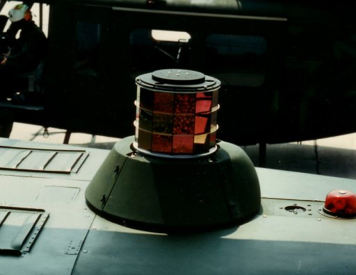
Sanders AN/ALQ-144 Infrared Countermeasures Set. Mounted above the tailpipe of an AH-1S Cobra attack helicopter, this ALQ-144 radiates modulated infrared light to jam the seekers of optically guided SAMs and AAMs. This compact 1200W DC/12.7 kg jammer is optimised for low/slow tactical aircraft with over 1300 sets installed on AH-1, AH-64, UH-1 and UH-60 helicopters. Note that this particular Cobra lacks the scabbed on optical detectors of the AVR-2 Laser Warning Receiver which is integrated with the AH-1's internal APR-39 Radar Warning Receiver. Part2/Pic 5 Loral MATADOR IRCM. The MATADOR infrared jammer was optimised for use on large jet aircraft such as airborne command posts, AWACS, VIP transports and tanker/ transports. Aft looking MATADOR transmitter LRUs are typically faired into the trailing edges of engine pylons or other structure adjacent to the engine tailpipes, with additional forward looking LRUs embedded in the wing roots to foil all aspect missiles. All transmitters are electronically synchronised by a central programmable controller unit.
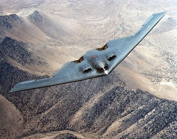
Northrop B-2A Advanced Technology Bomber. The bat-like B-2A defeats infrared trackers on threat aircraft and missiles by concealing the hot ends of its F-118-GE-100 turbofans with undulating narrow aperture tailpipes, while its exhaust plumes are cooled down to temperatures at which their infrared emissions are rapidly absorbed by atmospheric carbon dioxide and water vapour. With its extremely low radar cross-section the ATB is very difficult to detect and no less difficult to kill with conventional AAMs once detected. High Energy Laser Weapons The High Energy Laser (HEL) is a weapon which is within a decade of deployment, if development is sustained. While often ridiculed as science fiction technology, the current generation of near and mid-infrared chemical lasers has demonstrated usable power levels of hundreds of kilowatts and the ability to deliver power through beam folding optics to a beam director and target. The early eighties saw the demise of the USAF Airborne Laser Lab (ALL) program (see TE Dec 1981) during which a carbon dioxide 10.6 micron gas dynamic laser weapon on an NKC-135A airframe successfully engaged and shot down transonic drones. Objectives met, the funding was stopped. Work is however currently being done on the US Navy's land based Miracl deuterium fluoride 3.8 micron chemical laser which coupled to a Sealite beam director has been involved in successful trials against supersonic Vandal missile targets. The USN sees the HEL Weapon System (HELWS) as a shipboard point defence weapon with the ability to kill aircraft and missiles in a high density air/sea battle (interested readers are directed to USNI Proceedings Oct 1988). Coupled to Aegis battle management, optical fire control will be used. High power tunable Free Electron Lasers are also under development for SDI applications (Lawrence Livermore labs and TRW), but these devices are so huge that they are unlikely to be practical in air defence applications. Heatseeking and Imaging Weapon Guidance Heatseeking and imaging guidance have been used in missiles for over two decades. Heatseeking guidance has progressed from simple rotating reticle tail aspect only capable missiles to jam resistant flare rejecting all aspect weapons. The most recent variants of the established Sidewinder, the Mike and Romeo are described as substantially better than their predecessor, the Lima model which had a success rate of 86% in the Falklands conflict. Similarly heatseeking SAMs have progressed considerably, with the current FIM-92C Stinger offering a dual colour rosette scanning seeker with a field programmable guidance processor. The Russians have also expended considerable effort in this area with the new SA-13 Gopher fitted with a cooled dual colour seeker. All aspect heatseekers are thus a real threat to all classes of aircraft at all altitudes and trivial countermeasures such as flares are largely ineffective with newer weapons. Capable jammers, warning systems and sufficient aerodynamic performance to sustain manoeuvre are thus necessary for survival. Imaging missile guidance saw its first major application during the SE Asian conflict when the USAF demolished several communist targets with HOBOS TV guided bombs. Soon followed by the TV guided AGM-65A/B Maverick tank killing missile, imaging guidance found a wide range of applications all requiring pinpoint accuracy. Imaging weapons will employ either conventional television or thermal imaging to provide an operator with a view of the target. An automatic tracker is then used (as described above) to ensure that the weapon tracks the selected target until impact. Simpler weapons such as Maverick are Lock-On-Before-Launch where the launch platform flies to line-of-sight to the target, the operator then locks the missile on and launches it, more complex weapons such as AGM-84E SLAM and GBU-15 are Lock-On-After-Launch where a datalink carries the TV image to a remote launch aircraft. The latter family of weapons is about to expand with the deployment of optical fibre guided weapons which unwind a hair thin optical cable as they fly, this cable carries the TV image from a nose camera back to the launch platform which sends guidance messages back to the weapon via the same cable. Unjammable and electromagnetically silent, these weapons (missiles, glidebombs) will be used against aircraft, helicopters and surface targets. The Electro-Optical Defensive Suite Defending an aircraft against optically guided weapons and fire control systems will involve detection, tactical flying and jamming where applicable. Detecting an inbound missile or tracking by a hostile fire control system is a primary concern here for obvious reasons, and may be accomplished by several means. Optically guided missiles are passive and their only detectable emission is the heat of their exhaust plumes. Two strategies are therefore used for detection and tracking. The first is that of a missile warning radar which scans the airspace about the aircraft looking for returns with the appropriate Doppler for an inbound missile. The second strategy is the use of an infrared detection set which is a tracker optimised for detecting and tracking missile exhaust plumes. An example of the former strategy is the ALQ-156, its strength lies in its ability to estimate the range of the threat, its weakness is that it is broadcasting the location of the aircraft it is protecting. An example of the latter is the AAR-34 as fitted to the F/FB-111 or AAR-44 or 47 as fitted to C-130 aircraft. The latter strategy offers truly passive operation and should not compromise the position of the carrying aircraft. Detecting tracking by a hostile optical fire control system can be more difficult as its platform need not be easily detected. Thermal imagers and IRS&T sets in passive (angular) tracking mode cannot be detected unless one resorts to something drastic, such as scanning airspace with a laser and looking for glint off the infrared filter covering the threat's optics. Doing this may detect the bad guy but will certainly compromise your location. However if the bad guy is serious he will probably want to get range information for a fire control solution and will thus turn on his laser rangefinder thereby blowing his cover and intentions to a defending aircraft carrying a Laser Warning Receiver (LWR). Devices such as the Perkin Elmer AVR-2 Laser Warning Receiver are analogous to radar warning receivers in that they use a set of four suitable optical detectors and listen for the pulse trains associated with particular fire control systems or guided weapons, feeding warning information into existing aircraft/helo radar warning equipment. Once the threat has been detected defensive measures can be taken. The objective of these is to cause the tracker in the threat system to break lock. If the threat is a rotating reticle tracker (AAM, SAM, IRS&T) dropping flares may seduce the tracker, just as rotating the tailpipe away from the threat may break lock. The most effective strategy is however jamming with a device such as the Northrop AAQ-4, AAQ-8, MIRTS, Loral ALQ-123, MATADOR or Sanders ALQ-144. These devices typically use an alkali metal vapour (eg cesium) lamp which is electrically or mechanically modulated to flash with a selectable code known to interfere with the tracker in the threat system. A newer alternative may be the tunable free electron laser which could be tuned to the most sensitive colour of the threat tracker and jam it (as above). If the threat is an imaging tracker this may not be adequate and terrain masking (ie placing a hill between oneself and the bad guy) may be the only choice. A possible countermeasure as suggested above would be the use of a laser to damage or dazzle the threat tracker, the deployment of any such system has not been publicised in the open literature. The modern battlefield
environment is optically hostile and survival will eventually
necessitate the carriage of laser warning systems, infrared missile
detection equipment, infrared jammers and the wearing of laser
protective goggles by aircrew and footsoldier alike. The threat of
blinding by hostile and friendly laser equipment is very real on the
battlefield of the nineties and should be considered carefully . Unlike
situations such as nuclear, biological and chemical warfare which are
arguably unlikely to be encountered, optical weapons are here to stay. REFERENCES:
|
|||
|
|||||||||||||
|
|
|
|
|
|
|
|
||||||
|
|
|
|
|
|
|
|
||||||
|
|||||||||||||
| Artwork, graphic design, layout and text © 2004 - 2014 Carlo Kopp; Text © 2004 - 2014 Peter Goon; All rights reserved. Recommended browsers. Contact webmaster. Site navigation hints. Current hot topics. | |||||||||||||
|
Site Update
Status:
$Revision: 1.753 $
Site History: Notices
and
Updates / NLA Pandora Archive
|
|||||||||||||
|
|
Tweet | Follow @APA_Updates | |||||||||||
|
|
|||||||||||||
|
|
|||||||||||||