|
||||||||||||||||||||||
 |
||||||||||||||||||||||
 |
 |
 |
 |
 |
 |
 |
 |
|||||||||||||||
 |
 |
 |

|
 |
 |
 |
 |
|||||||||||||||
 [Click for more ...]") |
||||||||||||||||||||||
| Last Updated: Mon Jan 27 11:18:09 UTC 2014 | ||||||||||||||||||||||
|
||||||||||||||||||||||
|
||||||||||||||||||||||
|
||||||||||||||||||||||
|
|
|
|
|
|
|
|
|||||||||||||||
|
|
|
|
|
|
|
|
|||||||||||||||
|
||||||||||||||||||||||
| Last Updated: Mon Jan 27 11:18:09 UTC 2014 | ||||||||||||||||||||||
|
||||||||||||||||||||||
| ELECTRO-OPTICAL SYSTEMS | |||
|
|||
|
Though radar is an effective sensor, particularly in its advanced forms, it has a fundamental weakness as it requires that the transmitter illuminate the target with energy. In doing so it identifies itself and betrays its location, not to speak of its vulnerability to deceptive or other ECM. Electro-optical (EO) sensors, on the other hand, do not have these deficiencies, as they are entirely passive, sensing energy emitted by or reflected off the target itself. Compared to radar, EO systems are really newcomers to the field of warfare, the first serious application being the use of FLIR (Forward Looking Infra-Red) systems during the VietNam war, to provide gunship crews with night vision. FLIR proved to be a great success, enemy personnel and equipment betraying their location with their own heat emissions. This led to a substantial increase in development, yielding a broad family of FLIR systems by the late seventies. Viet Nam also saw to the development of another family of EO system, the stabilised TV telescope. One of the basic aspects of the air war over Hanoi was the necessity to visually identify hostiles prior to weapon launch (a very rational approach bearing in mind the low reliability of IFF [Identification Friend Foe] systems, as used at the time). This however placed the larger US aircraft at a significant disadvantage, as the NVAF MiGs would see them first and thus had the option of initiating the engagement on their own terms. With the following generation of fighters, the F-14 and F-15, being even larger than the well sized Phantoms and Thuds, the Americans were confronted with a ridiculous situation - sophisticated weapon systems with standoff missiles being forced into close quarters dogfights with vastly inferior but small and nimble Russian fighters. The TV telescope reversed the situation, allowing reliable visual identification at ranges beyond those necessary to even detect the target with the naked eye. A further step in EO system development was the subsequent coupling of an EO system, FLIR or TV, with a laser designator. Boresighted with the EO device, this enabled the recognition and subsequent laser illumination of surface targets, allowing surgical strikes with laser guided munitions. With increasing performance and decreasing cost, EO systems also began to proliferate into the area of missile guidance, resulting in the Maverick and Walleye families, followed up by the heavyweight GBU-15 weapons. This trend toward EO target recognition and EO guided weapons does appear to be accelerating. The last word is the Focal Plane Array (FPA), a tiny slab of semiconductor material that behaves as a single chip TV imaging device, infrared or visual. FPAs are more compact, robust and reliable than conventional vidicon based systems and have the potential to offer far superior performance at substantially lower mass production costs. These characteristics will allow the development of an entirely new generation of standoff weapons, built around FPAs and high powered signal processing chips. These weapons will dispense hundreds of intelligent submunitions, each with the ability to see, recognise and prioritise targets independently of the launch vehicle or mother projectile. The ultimate implications of advanced EO technology are staggering, even in comparison with today's impressive hardware. Current systems are quite sophisticated, as the reader will shortly come to appreciate. Television Systems - A Black Box Model The purpose of a television (TV) system is to transmit a two dimensional image and reproduce it in a form viewable by an operator. In this day and age TV systems may assume a multitude of forms, utilising a wide range of image conversion, coding, transmission, decoding and display techniques. In spite of these variations all systems have a number of common features, and these are summarised in the black box model of Figure 1. (For those readers familiar with analogue vidicon /CRT TV, the author offers his apologies, FPA and planar display technology both utilise architectures very close to this model.) As is apparent, the observed image (rather target, here a MiG) is focused by optics into the plane of the imaging device. In this fashion the 3-D spatial image is contracted into a 2D picture. This must now be transmitted in some form to the operator's display. In conventional film cameras, the whole image is recorded simultaneously and reproduced simultaneously, with a fixed number of frames being shown every second. Due to the slow response of the human eye, one need only show 25 frames per second to create the illusion of smooth and continuous motion. Any slower rate could be seen as flicker, any faster rate is uneconomical as the eye doesn't really know the difference. This rate at which image frames are changed is termed the refresh rate. TV systems, just like cinema, must refresh the image periodically. In TV however, one cannot really change all of the picture at once. This is because we would need to transmit all of the picture simultaneously and that is clumsy. TV employs a different approach. The image is broken up into tiny rectangles, so tiny that they are smaller than the smallest discernible feature in the object we are viewing. Each of these rectangles, termed picture elements or pixels, thus has a uniform brightness (and/or colour) all over its surface. In this fashion the image can be broken up into an array of individual brightness samples. Having done this, we may proceed to transmit the image, pixel by pixel. The black box behind the imaging device plane is a multiplexer, this box will select whichever pixel it is told to access, and channel its brightness sample through the transmission link. Conventional TV scans the pixels line by line (ignoring interlace), starting at the top, say left hand corner, scanning to the end of the line, then jumping back to the beginning of the second line and repeating the process until the whole image has been scanned, top to bottom. All of this must of course happen within the short period of
time allocated to that particular frame. The process is thus repeated,
say 25 times a second. Here is where one of the troublesome aspects of
TV becomes apparent. Consider an array of say 488 x 380 pixels. To
transmit a continuous TV picture we must then transmit around 185,000
brightness samples 25 times a second and that is a lot of information
(around 2000 voice channels). The problem is unfortunate as the finer
the resolution (or higher the pixel density) or quality of the picture,
the greater the channel capacity required, which translates into faster
and thus more expensive electronics.
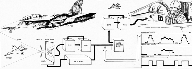
Generic Model for an Electro-Optical System. This represents a typical scenario involving the use of EO systems for target identification. The F-18 aircraft (here perhaps a IaterA-18 model with SAR groundmapping radar) is on a deep strike mission, armed with CBUs for defence suppression. The aircraft would use FLIR to precisely resolve and identify ground targets, prior to attack. However, hostile air defence aircraft are encountered (here a MiG-29 Fulcrum) and are identified by TCS allowing standoff launch of the all aspect AIM-9L missile. TCS and related EO systems provide air superiority fighters with the means of identifying hostiles outside of visual range. The EO system outlined would use optics to focus the target image onto the face of an imaging device. This area is divided into an array of M x N pixels, each of which is sensitive to brightness levels. The brightness is thus read off at each pixel, pixels accessed in some particular scan pattern (see text) by the multiplexer (MUX) which is controlled by the synchroniser (SYNC). The result is a video signal, containing image and synchronising information, which is channelled to the pilot's Head Down or Head Up Display (HDD or HUD). This transmitted image may undergo enhancement processing, to emphasise some aspect of the target. The display receives brightness information at each pixel, as determined by the synchroniser which analyses the incoming signal, extracting sync information to control the multiplexer and thus select pixels. The Instantaneous Field Of View (IFOV) of modern EO systems is very narrow, usually of the order of 1.5 to 0.5 degrees of arc. Autotrack capability is now standard in most systems. (Illustration by Mark Kopp)
To complete the transmission process, the brightness samples are then channelled to the appropriate pixels in the display device. The screen of the display device then emits light (or reflects it) at a level proportional to the size of the brightness sample at each respective pixel. The operator then views this either directly or through a collimating lens which focuses the image at infinity (e.g. F-18 HSD). As is apparent, the addressing (or accessing) of the pixels must be done in an ordered fashion; this is the task of the synchroniser, which controls the multiplexer and also adds synchronising information to the brightness sample information. This synchronising information is then extracted by the synch roniser associated with the display and used to channel the brightness information to the appropriate pixel location. Thus one can piece together the picture at any distance from the imaging device, subject only to the quality of the information at the end of the transmission link. Practical TV systems fall into two categories, analogue and digital. In analogue systems the brightness information is transmitted as a continuous signal, going up and down, pixel by pixel, line by line. Synchronising information is added as pulses at the end of each line and each frame. Conventional commercial TV uses 625 lines, whereas military systems use finer resolution, e.g. 875 lines (EIA video signal). Digital systems transmit the brightness of each pixel as a number, using some particular coding technique. The result is a stream of coded numerical information, interrupted occasionally by specific synchronisation codes. For full brightness resolution one would use 8 bit (binary) samples for each pixel, though compression techniques and crafty coding can squeeze it into a lot less. This model of a N system is very general and really only outlines the functional purpose of each block. Practical systems are implemented with highly diverse forms of technology, whether one looks at imaging devices or displays. Display Technology Though the display is the last link in the chain, we will examine it first, as the first link may assume various forms, e.g. FLIR or TV telescopes. Displays come in two basic forms, head up or head down (HUD or HDD, please refer TE, March 1981). Either way, they require some sort of imaging device to convert the electrical video signals into a picture. Typical of these is the venerable Cathode Ray Tube (which the reader may find inside any common TV set). The CRT though conceptually old, is still very strong and outperforms most of its newer rivals with effortless ease. The physical principle which is exploited is the property of some substances, termed phosphors, which glow when bombarded with a stream of accelerated electrons. In a CRT, a beam of accelerated electrons scans over a phosphor coated screen, line by line. The intensity of the beam is proportional to the brightness of the pixel location it is pointing at, at any given time. In this fashion, the image is recreated as variations in phosphor brightness. The weakness of the CRT lies in its demand for a lot of support hardware (though not really complicated, by necessity cumbersome to package). High voltage sources are required (e.g. 25,000 V) to accelerate the electron beam, focus it (cca 1000 V) and deflect it (cca 800 V) for magnetic line deflection). The CRT itself is a large glass tube containing a relatively high quality vacuum, thus it is vibration and shock sensitive and hazardous when ruptured (the author doesn't recommend trying it ... ). The geometrical precision of the picture is dependent upon the precision of the deflection components and absence of stray fields. A further nastiness is the CRT's tendency to radiate interference (above high voltage sources) which may upset other sensitive equipment. In spite of these drawbacks, it is very popular, being well understood. Current systems represent the pinnacle of CRT development, being rugged, robust and compact with very good picture quality. The cockpit environment is demanding: vibration, temperature changes, g-forces, shock loading and bright outside illumination all doing their best to impair picture quality. Outside brightness levels have to date restricted the use of many potential candidates for cockpit displays, bright sunlight levels (cca 3.5 cd /cm2) simply washing out the light output of the display. The Light Emitting Diode (LED) array falls into this category, only recently becoming viable (Litton Canada). LED arrays are compact, rugged solid state flat panels made up of an array of individual LEDs (these emit light when electrical current passes through them) and addressing chips, which selectively control the brightness of each LED/ pixel. These devices are exceptionally well suited to alphanumerical (status/data) displays and consume little power or space. Another candidate which may become viable is the Liquid Crystal Display, a passive (non-emissive) device commonly found in $3 calculators. LCDs consume negligible amounts of power and are neat and compact. Unfortunately they have difficulty coping with the Mil temperature range spec and tend to have inadequate contrast under subdued lighting.
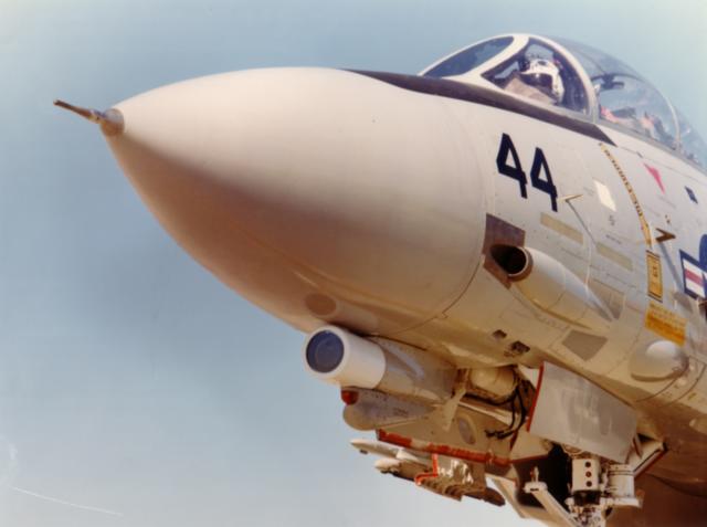
Northrop AN/AXX-1 Television Camera System (TCS). TCS represents the TISEO/TCS family of stabilised TV telescopes, used by the USAF and USN on air defence and air superiority fighters. TCS provides sharp close-up images of hostile aircraft outside of visual range. Typical identification ranges quoted are. DC-10 at 85 miles, F-111 at 40 miles, C-130 at 35 miles and F-5 at 10 miles. TCS could be fitted to the F-18, though currently only the F-14A is equipped. Below installation on F-14D with IRST (Northrop images).
A promising candidate, at this stage, is the DC plasma display (e.g. Siemens AG, Germany). This is a flat panel display, using a phosphor screen much like a CRT. However it is filled with low pressure gas and equipped with rows and columns of individually addressable electrodes, each intersecting at a pixel location. Applying the appropriate voltages generates a discharge at the desired pixel location, the electrons thus strike the phosphor and generate a picture just as in the CRT This display has the potential to match the performance of the CRT, but uses far less space, being only 2.5" thick, and far less power. Currently brightness and contrast seem to be the problem (perhaps also sensitivity to vibration) [Editor's Note 2005: outgassing of cathodes in plasma displays continues to impair durability of this otherwise excellent display technology]. Significantly, phosphor based systems have substantially better hardness against nuclear attack (radiation/EMP), compared to solid state devices and this is important as one can hardly bury a display under screening panels. Display technology is currently entering a new phase of development, with the deployment of helmet mounted projection visors (Honeywell IHADSS, Hughes PNVS). These use compact CRTs to project imagery onto the pilot's visor and thus avoid the need to dedicate instrument panel space for displays. Alternately, they allow the presentation of greater amounts of information without complicating the operation of existing displays. What one could expect to see in future systems is the use of large flat panel displays, carrying status information, threat information, radar pictures or maps. Time critical data, such as attitude indicators, flight parameters and EO images will then appear in HUDs or helmet visors, subject very much to the mission and vehicle [Editor's Note 2005: the as yet vapourware JSF cockpit display is the only genuine example, illiustrating how slowly these technologies have actually matured].
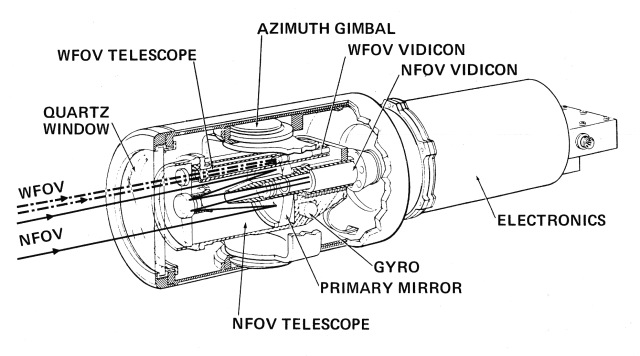
TV Telescopes - TISEO and TCS The TV telescope is one of the simplest EO systems. In spite of this it is an extremely effective tool, as outlined earlier, and when integrated sensibly with other components of an aircraft's weapon system offers far more than meets the eye. The most common system in use today is the Northrop AN/ASX-1 Target Identification Set Electro-Optical, commonly known as TISEO. This system entered service in the seventies with the USAF, being fitted initially to the F-4E and later to the F-15. This basic technology was subsequently refined and used to develop the AN/AXX-1 Television Camera System (TCS) for the US Navy's F-14 air defence fighters, to enhance their capabilities in air superiority. Both TISEO and TCS represent the first major generation in TV systems and as such are built around the established vidicon. The vidicon is a vacuum tube imaging device and employs similar technology to the CRT In vidicons, or related imagers, one utilises a similar pixel scanning technique as in the CRT, however in this instance the optical image is used to change the charge density, from pixel to pixel, on the surface of a slab of semi-conductor. The impinging electron beam then neutralises the charge at each pixel; by sensing the excess beam current one can sample the charge at the pixel location and thus the brightness. The vidicon has most of the vices of the CRT albeit to a lesser degree due to smaller size and more compact layout. Modern vidicons (or plumbicons) are small, compact and surprisingly cheap (often around $200) though a Milspec version might bite into one's budget. The AN/AXX-1 TCS uses two separate vidicons (see diagram), one for a narrow field of view, the other for a wide field of view. TCS is split into two Weapon Replaceable Assemblies (WRA), the actual telescope and a separate black box full of electronics. The telescope itself is housed in a cylindrical cover, protected by a thick quartz window. The two vidicons and their respective optics are mounted on a stabilised and gimballed assembly which allows the telescope to point in any direction within a 30 degree Field of View (FOV), centred on the axis of the aircraft. The gimbal may be slewed at rates beyond 30 degrees/sec and the stabiliser will isolate the assembly from aircraft pitch/yaw rates up to 150 degrees/sec. These characteristics allow the telescope to acquire and track targets within the 30 degree cone ahead of the aircraft, irrespective of turbulence and manoeuvring (within limits, of course). The telescope itself has two instantaneous fields of view, as stated. For wide field of view (WFOV) it uses a conventional lens based telescope and a dedicated 5/8" vidicon (see upper part of diagram), providing a viewing angle around 1.5 degrees. Looking closely at a target, TCS uses its narrow field of view (NFOV) assembly, built up with a compact cassegrainian (mirror) telescope with a somewhat larger vidicon (1") than the WFOV assembly. This arrangement brings the viewing angle down by a factor of three and it is this mode which is employed for identifying targets. The optics represent only a part of TCS; one of its most powerful features is an automatic video tracker. The tracker is an electronic system which locks onto a particular feature in the viewed scene and compares its location in the FOV from frame to frame. This enables it to detect the motion of the target and keep the telescope pointed at it. Another feature of TCS is its ability to scan a scene until it locates a would-be target, which it locks onto and tracks. These abilities are further enhanced by the tie in with the F-14's AN/AWG-9 fire control radar. The radar may be slaved to the TCS line of sight (LOS) or TCS may be slaved to the radar. This characteristic provides a flexible system with a good ECCM capability. Consider a penetrating Backfire. Detected by the AWG-9, the F-14 slews the TCS onto the Backfire to identify it. Identified, the F-14 then commences illuminating for a Sparrow launch. The Backfire identifies the radar mode and directs most of its jamming power onto the F-14. The AWG-9 cannot match the power and burn through, it therefore loses lock. Will the Backfire get through? No, as the F-14 slaves the AWG-9 to the TCS LOS and engages the video tracker. Though the AWG-9 can't see what it's illuminating, it is illuminating the target tracked by the TCS system. A Sparrow launch may then proceed. As is apparent, TCS is a very useful air defence tool, allowing standoff missile launches (and finally the use of Sparrow and Amraam for what they were designed for), raid size assessment, undetectable target acquisition, tracking, identification and the above detailed ECM penetration technique. After missile launch the fighter crew may assess damage to the target. Though these gains are significant, they hardly measure up to the gains acquired in the air superiority role. In classical VFR air combat scenarios, TCS allows visual ID of approaching aircraft at three to seven times the range necessary for unaided visual ID. Once tracking the TCS operator may easily and instantaneously observe the target's offensive or evasive manoeuvring, including missile launches. All of this outside of visual range (interested readers are referred to March '82 issue, P83). Quoted identification ranges are F-111 at 40 nm, C-130 at 35 nm, and F-5 (mean) at 9.9 nm, the quoted first missile firing range was more than doubled. The system is also fitted with a video recorder and this aids in postflight analysis of engagements, aside from its obvious use as a recce tool. TCS is currently being fitted to USN F-14s, where squadrons
will be provided with a mix of TCS equipped and non equipped aircraft.
Some sources suggest TCS may also be fitted to the F-18, though no
official USN statements to that effect seem to have surfaced, to date.
Were that the case, it would be a sensible acquisition for the RAAF's
F-18 force.
TI
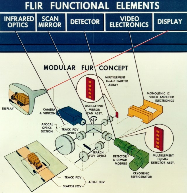
Artwork Forward Looking Infra Red Systems Born into this world some twenty years ago, FLIR has reached maturity. Texas Instruments prototyped the first FLIR system in 1964, utilising experience acquired in the development of IR line scanners for recce applications. The first combat application of the new FLIR then took place in 1967, to the detriment of the Viet Cong. Early FLIR systems were dedicated to specific applications and thus expensive to support; recognising this the US DoD subsequently introduced the common module concept in 1974. This meant that all FLIR systems were built up of standardised components and modules (be it optical or electronic). These modules are then used to build up the essential assemblies and black boxes used in actual systems, such as FLIR pods. FLIR systems are by nature much more complex than simple TV; TV is in fact used as part of the system. Essentially the generation of FLIR imagery occurs in two steps. Firstly, IR energy is appropriately focused and then converted into visible light. This light is subsequently used to convey the image to a suitably adapted TV system. The reason why infrared is used for target detection is its inherent association with heat - as objects warm up, their molecules vibrate more rapidly; as they vibrate, their associated electric fields (at an atomic level) vibrate and thus emit, in varied ways, photons of low energy radiation. These photons are infrared light (see TE, March 1982, for details) and all objects at reasonable temperatures radiate it. Therefore it is possible to use this for detection and imaging. Furthermore sunlight has a large IR component and also heats objects, forcing them to radiate. The overall effect is that a whole landscape, including targets, radiates IR and because no two objects will have the same temperature, each will radiate varying amounts. FLIR may then be used for day and night operation, the only difference to the operator being in the need to set different contrast levels on his screen. A further asset of IR is its ability to propagate through haze, smoke and some forms of water precipitation that obstruct visible light (FLIR systems operate in the 10 um band, utilising the 8 to 14 um window, this encompassing blackbody radiation associated with hundreds of Kelvin temperatures). A FLIR system (see diagram), initially filters out visible and undesired infrared light with a special window (usually an interference filter, hence the mirror look). The 'cleaned up' (spectrally) IR then enters the optics, which provide specific viewing angles (usually NFOV and WFOV) for specific systems, the optics are usually changed mechanically. The focused image then falls upon a rotating or oscillating mirror, which together with optics focuses a thin vertical slice of the image on to a vertical array of IR detector elements. These detector elements are tiny pieces of Mercury -Cadmium-Telluride (MCT), a semi-conductor which is very sensitive to 10 um band IR light. For the same reason that HgCdTe is sensitive to IR, it is also sensitive to temperature and therefore must be cooled down to ensure that the thermal vibrations in the material do not swamp the effects of the detected radiation. For these reasons the detector array is contained in a Dewar module with a cryogenic refrigerator, this arrangement maintaining a constant 77 K (or -200 deg. C) temperature. The IR impinging upon the array of detector elements generates an electrical signal, which is fed to a geometrically identical array of visible band LEDs, which thus emit a thin slice of a visible image corresponding in brightness to the detected slice of the IR image. This is then reflected by the other side of the mirror into a vidicon, which generates a TV image for the viewer. The elegance of the system lies in the simple and inherently accurate synchronisation of the IR and visible scans by using both sides of the scanning mirror. The line scanning of the vidicon is then slaved to the rotation of the mirror, thus scanning only the line illuminated by the slice of the scene. Obviously, the process is a trifle more complex, as it is necessary to stabilise the optics, precisely control mirror speed, control the gain of the video amplifiers which boost the detector output to drive the LED emitters and also maintain precise temperature control. It is for these reasons that FLIR systems are essentially bigger, heavier and more complex than common TV. A typical FLIR system is the AN/AAQ-9, the principal element
in the RAAF's new AN/AVQ-26 Pave Tack pod, currently being fitted to
the
F-111C. The AAQ-9 is a large black box, containing the FLIR and optics,
and a separate electronics module. A separate computer, video recorder
and autotracker (itself a compact black box with more than 10 PCBs)
complete the signal handling part of the system (Pave Tack will be
detailed in a future article). It is currently customary to couple FLIR
with lasers, for range finding and designation, and often laser spot
trackers (TRAM). Significantly, there exist also techniques to enhance the readability of the FLIR image, otherwise much like black and white TV with unusual tones. One of these is edge enhancement, which sharpens up the image, another is 'hot black', which inverts the picture to a negative with the hottest images darkest. If the aircraft is fortunate enough to use a full colour CRT or display, one can also use false colour. False colour systems assign a colour to each shade of grey. As these shades of grey each correspond to particular scene temperatures, one can selectively highlight parts of the scene with specific temperatures. In simpler terms, a landscape can be painted in cool greens and blues, whereas vehicles and installations can be displayed in hot reds, oranges and yellows, tailored to each particular family (or even type) of target. Targets will then stick out like the proverbial sore thumb, needing only close examination for exact identification, prior to attack. It is almost certain that the next generation of FLIR systems in use will employ these and other image enhancement techniques, even so, current systems such as the RAAF's Pave Tack and AAS-38 (F/A-18A FLIR pod) are highly potent force multipliers and as such are an excellent means of cost effectively stretching resources. Focal Plane Arrays The FPA is the emerging successor to current EO systems and will offer quantum improvements in both optical performance, size and ruggedness. There are two broad families of FPAs, discrete and monolithic. A discrete FPA is comprised of a slab of an electrically insulating material with an array of individual detectors either glued or otherwise deposited on its surface. Signal processing chips (here virtually only the die) and connections are then also attached, creating a hybrid module. The detectors may have any particular geometrical layout the user requires, though most commonly rectangular or square. Discrete FPAs have an advantage over monolithic arrays as one can optimise the performance of the detectors, signal processing and addressing chips (say use Silicon for signal processing, amplification, addressing and HgCdTe for detectors), in a monolithic array all must be of one material. The penalty paid for this advantage is severe, as the cost is far higher (it takes a lot more time and effort to glue down and test say 32 x 32 detectors and extras) and the packing density far lower. It is therefore likely that these devices may find more use
in
weapon guidance. Monolithic FPAs are far cheaper, particularly due to
their fabrication process, as they use a single slab of semiconductor.
Functionally, either device simply uses a detector for each pixel and
employs supporting electronics to read the brightness levels at each
pixel in a predetermined scan pattern, e.g. TV linescan. FPAs are
however much easier to support than vidicon based TV and mechanically
scanned FLIR, as most of the timing, control and level amplifying
electronics are very compact (and often on the same substrate) and
consume little power. The only outside support required is
refrigeration
(i.e. placing the whole FPA into a Dewar module, or glueing it on to a
thermoelectric Peltier solid state refrigerator) and of course
mechanical stabilisation.
Amber
Engineering Focal Plane Arrays (Amber Engineering). Monolithic FPAs come in two basic families, the simpler CID (Charge Injection Device) and the more sophisticated CCD (Charge Coupled Device). The CID has a simpler architecture and is thus more suited to HgCdTe IR arrays; as such it is more dependent upon outside chips (HgCdTe can be a troublesome material to work with, it is therefore inconvenient to try to fabricate support circuits on the same chip as the detectors). The CCD imaging array contains all the necessary support circuits and as such is a complete TV camera, needing only a lens and wires to connect up the power and a timing reference (sync). CCDs are commonly fabricated in Silicon, therefore they are suited only to the visible band (peak sensitivity in the near IR at 800 m, virtually red), but they do offer superb sensitivity under low light levels, enough to rival some forms of Low Light TV (LLTV - basically a TV camera with an image intensifier). CCDs exploit one of the more interesting properties of semi conductors. Consider the following. Given a slab of Si, we deposit a thin layer of oxide, upon which we deposit a set of metallic electrodes (here a row of tiny rectangles of Aluminium, each rectangle is an electrode). Each electrode thus becomes, together with the oxide and semiconductor, a tiny capacitor, which can store electrical charge. Now consider that all but the first capacitor are empty, the first containing a packet of charge. If we appropriately control the electrical voltages applied to each electrode, we can actually induce the packet of charge to jump from beneath the first electrode to the second. Repeating this, then from the second to the third, third to fourth until we reach the last electrode. If we did everything correctly, we would still have the same packet of charge left (minus perhaps a few electrons lost on the way). In this fashion we have shuffled it from one point on the slab to another, much like a bucket brigade (the often used term for CCDs). It is this technique that is exploited in the CCD, as such laneways are integrated onto the same chip as the detectors. In fact, such rows of electrodes lie alongside rows of detectors (in pixel locations); these rows in turn end at another laneway, much like a comb layout. By craftily controlling the applied voltages, it is possible to suck charge packets out of each detector site (hence brightness samples) and transport them away along a laneway, for all columns simultaneously. By arranging the laneways correctly, it is then possible to simply read the charge at a single corner of the slab, packet by packet, as a series of pixels, pixel by pixel, scanned in the appropriate pattern. Electro-optical systems have matured and are about to burst
out in a huge variety of new applications, whether as sensors or
guidance systems. It is not easy to clearly determine the exact path
which development will follow, but one thing is very clear -
electro-optical systems are on the rise. |
|||
Further Reading:
|
|||
|
|||||||||||||
|
|
|
|
|
|
|
|
||||||
|
|
|
|
|
|
|
|
||||||
|
|||||||||||||
| Artwork, graphic design, layout and text © 2004 - 2014 Carlo Kopp; Text © 2004 - 2014 Peter Goon; All rights reserved. Recommended browsers. Contact webmaster. Site navigation hints. Current hot topics. | |||||||||||||
|
Site Update
Status:
$Revision: 1.753 $
Site History: Notices
and
Updates / NLA Pandora Archive
|
|||||||||||||
|
|
Tweet | Follow @APA_Updates | |||||||||||
|
|
|||||||||||||
|
|
|||||||||||||